|
<< Click to Display Table of Contents >> Interferometry - Clustered Processes - Stereo Cluster |
  
|
|
<< Click to Display Table of Contents >> Interferometry - Clustered Processes - Stereo Cluster |
|
Purpose
This tool aims to include the Stereo Matching Process and the Shift to Height Conversion and Geocoding in single step exploiting the capabilities of SARscape cluster (if enabled and licensed). As a function of cluster nodes, the full area is splitted in more subareas and each subarea is processed. A mosaiced final result is obtained.
Stereo Matching Process functionality is intended to estimate the elevation by means of the amplitude (intensity) data in a stereo-matching workframe.
Shift to Height Conversion and Geocoding functionality is intended to re-combined the absolute calibrated shift with the synthetic shift and it is converted to height and geocoded into a map projection. This step is performed in a similar way as in the geocoding procedure (Basic module), by considering the Range-Doppler approach and the related geodetic and cartographic transforms. The fundamental difference with the geocoding step is that the Range-Doppler equations are applied simultaneously to the two antennae, making it possible to obtain not only the height of each pixel, but also its location (Easting, Northing) in a given cartographic and geodetic reference system.
As result of this step also the coherence image is geocoded.
Technical Note
Stereo Matching Process
As for photogrammetry, also radargrammetry exploits a stereo acquisition configuration to estimate a precise topographic height. Data in slant range (_pwr or _slc) or ground range (_gr) are supported. In case of _pwr files, users have to mooltilook range 1: azimuth 1. The software retrieves a shift in pixel, along the range direction, that is proportional to the topographic height. The first step of this tool is to consider the known topography by coregistering the Secondary acquisition over the Reference acquisition. The residual mismatch (in range direction) will correspond to the residual topography with respect to the reference DEM. The matching algorithm is performed in a pyramidal way, by estimating an initial coarse shift on the multilooked acquisitions and refining it iteration by iteration to obtain a finer estimate.
The separation angle between the two acquisition should be between 15 to 25-30 degree. The higher the separation angle, the higher the sensitivity to the topography, while presenting the matching algorithm with a harder task. The radargrammetry tool can provide good results with high resolution sensors, and mostly in natural areas.
This estimate of the shift is performed by means of a coregistration process using the amplitude cross correlation (refer to the relevant Technical Note for details). The values of the output cross correlation vary between 0 (worst conditions) and 1 (best conditions), same as the coherence product.
The relationship between the Signal to Noise Ratio (SNR) value and the coherence (γ) value is:
SNR = γ2/1-γ2
The shift is calculated with steps (in terms of number of pixels) defined by the "Azimuth Looks" and "Range Looks" factors. We suggest using factors which are five times bigger than the default ones used in the multilooking process.
The coregistration shift estimate is optimized by means of the input Digital Elevation Model.
A flattening process is executed to remove the systematic effects due to the topography. It is executed by transforming the input Digital Elevation Model into the Reference slant range image geometry. In case of precise orbits and accurately geocoded reference Digital Elevation Model, this process is run in a fully automatic way.
It is important to note that:
❖the Reference file should be the image characterized by the higher spatial resolution (as a consequence of the higher incidence angle)
❖In case the "Input Reference file" has already been corrected with the manual or the automatic procedure the "GCP file" is not needed.
❖In case the "Input Reference file" is correct (i.e. the nominally geocoded image fits with the DEM), while the orbital parameters of the "Input Secondary file" are not accurate (i.e. the nominally geocoded image does not fit with the DEM), the "GCP file" is not needed but the flag "Automatic Secondary Orbit Correction", in the Preferences>Flattening, must be checked.
Shift to Height Conversion and Geocoding
The shift between Reference and Secondary data is calculated in pixel units and it is measured in the satellite viewing geometry.
The shift-to-height conversion is performed with a forward transformation. The calculated X, Y, Z Cartesian coordinates (and thereafter map coordinates) are transformed into the coordinates of the output DEM exclusively using a Nearest Neighbor approach.
Two files are generated in this step, beside the Digital Elevation Model and the geocoded coherence image, for a further use in the data mosaicing. They are:
- Precision, which is derived from parameters such as cross-correlation, baseline and wavelength. It provides an estimate (i.e. standard deviation value) of the measurement precision. The higher this value the lower the measurement precision. The formula used for the precision calculation is:
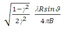
- Resolution, which represents the pixel resolution in ground range, that is:
pixel spacing slant range
sinϑ
where γ is the intensity cross-correlation, λ is the wavelength, R is the slant range distance, ϑ is the local incidence angle.
- Spatial Wavelet Size
The Height Wavelet size, expressed in meters, define what is kept of the residual topography estimated from processing data resolution till the specified resolution value. It removes the low pass distortion under the set resolution value by using wavelet decomposition.
- Data Interpolation is intended to assign a specific value to the dummy (NaN) pixels. The "Relax Interpolation" model is represented by a soft surface, which is adapted to the dummy surrounding area. The algorithm, which is based on the solution of the heat transfer equation (Poisson equation), uses known height values to reconstruct at the best the unknown topography; for this reason it is optimally suited to interpolate small zones, especially where abrupt morphological changes (i.e. steep slopes) are not present.
- Generate Shape format allows representing the DEM as a point cloud. This procedure is intended to preserve the actual pixel value without applying any interpolation, which is the case of the raster output. This format is the one to use as input for the Point Cloud DEM Fusion and for the Point Gridding. It can happen that the .shp and the .dbf become very large when there are a lot of valid points
The input DEM cartographic project corresponds to the cartographic projection of the output DEM.
Input Files
Input Reference File
File name of the Reference data (_slc, _pwr, _gr). This file is mandatory.
Input Secondary File
File name of the Secondary data (_slc, _pwr, _gr). This file is mandatory.
Optional Files
Geometry GCP file
Either a previously created Ground Control Point file (.xml) is loaded (Load GCP File) or the interface to create a new Ground Control Point file is automatically loaded (Create GCP File, refer to the "Tools>Generate Ground Control Point" for details). This file is optional.
Shift Parameter file
Name of the file with the shift parameters used for the coregistration (_par). This file is an output.
DEM/Cartographic System
Digital Elevation Model file
Digital Elevation Model file name. This should be referred to the ellipsoid. In case a list of input files is entered, the DEM must cover the whole imaged area. This file is optional.
Output Projection
In case that the Digital Elevation Model is not used, it is mandatory to define the Cartographic System.
To use the same coordinate system as another dataset, click the Import from Existing Dataset button and select the source dataset.
To apply the same Coordinate System of the current selected layer
The reset icon allows to reset the coordinate system field.
Parameters - Principal Parameters
Range Looks
Number of looks used to average the shift estimate in range direction.
Azimuth Looks
Number of looks used to average the shift estimate in azimuth direction.
Grid Size for Suggested Looks
The grid size, in meters, used to tune range and azimuth looks. If the other parameters are manually set, the grid size will not imply a change in their values.
Product Coherence Threshold
Pixels with coherence values smaller than this threshold will be set to dummy (NaN) in the final products.
Spatial Wavelet Size
The Height Wavelet size, expressed in meters, define what is kept of the residual topography estimated from processing data resolution till the specified resolution value. It removes the low pass distortion under the set resolution value by using wavelet decomposition.
Generate Shape format
By setting this flag the DEM is generated in vector (.shp) format.
Subarea overlap (%)
Percentage that defines the overlapping area among the sub areas.
X Dimension (m)
The grid size of the output data in Easting (X) must be defined; the default unit of measure is meters.
Note that - for the Geographic projection - if values higher than 0.2 are entered they will be considered as metric units and then automatically, and roughly, converted from meters to degrees; if values lower than 0.2 are entered they will be considered as degree and used as such without any conversion.
Y Dimension (m)
The grid size of the output data in Northing (Y) must be defined; the default unit of measure is meters.
Note that - for the Geographic projection - if values higher than 0.2 are entered they will be considered as metric units and then automatically, and roughly, converted from meters to degrees; if values lower than 0.2 are entered they will be considered as degree and used as such without any conversion.
Parameters - Cluster
It brings to the general section of the Preferences parameters. Any modified value will be used and stored for further processing sessions.
Parameters - Global
It brings to the general section of the Preferences parameters. Any modified value will be used and stored for further processing sessions.
Parameters - Flattening
It brings to the flattening section of the Preferences parameters. Any modified value will be used and stored for further processing sessions.
Parameters - Coregistration
It brings to the coregistration section of the Preferences parameters. Any modified value will be used and stored for further processing sessions.
Parameters - Geocoding
It brings to the geocoding section of the Preferences parameters. Any modified value will be used and stored for further processing sessions.
Parameters - Other Parameters
It brings to the general section of the Preferences parameters. Any modified value will be used and stored for further processing sessions.
Output Files
Output Root Name
Name of the output root. This file is mandatory.
_par
ASCII file containing the coregistration shift parameters in range and azimuth. This file is generated only if the shift parameters are calculated.
_orb.sml
Xml file containing the scene orbital parameters.
_orbit_off.shp
Shape file with the points used to estimate the orbit based shift. This file contains the following information:
| - | Pixel position in range direction (Range), in Single Look pixel units. |
| - | Pixel position in azimuth direction (Azimuth), in Single Look pixel units. |
| - | Shift measured in range direction (Dr), in Single Look pixel units. |
| - | Shift measured in azimuth direction (Da), in Single Look pixel units. |
| - | Calculated polynomial shift, to apply in range direction (Drfit), in Single Look pixel units. |
| - | Calculated polynomial shift, to apply in azimuth direction (Dafit), in Single Look pixel units. |
The file, which is generated only when the shift parameters are calculated, is multilooked (i.e. Azimuth and Range looks) as specified in the Input Parameters.
_dem
Digital Elevation Model with the associated header files (.sml, .hdr). The input DEM cartographic project corresponds to the cartographic projection of the output DEM.
_dem.shp
Digital Elevation Model in shape format and associated header files (.sml, .hdr).
_cc_geo
Geocoded coherence with the associated header files (.sml, .hdr).
_precision
Estimate of the data quality with the associated header files (.sml, .hdr). This file is used during the Digital Elevation Model mosaicing (Tools).
_resolution
Spatial resolution based on the local incidence angle with the associated header files (.sml, .hdr). This file is used during the Digital Elevation Model mosaicing (Tools).
Details specific to the Units of Measure and Nomenclature of the output products can be found in the Data Format section.
Referencefilename_ID
Reference file subarea characterized by the relative ID. The ID depends on the cluster nodes.
Secondaryfilename_ID
Secondary file subarea characterized by the relative ID. The ID depends on the cluster nodes.
General Functions
Exec
The processing step is executed.
Store Batch
The processing step is stored in the batch list. The Batch Browser button allows to load the batch processing list.
Close
The window will be closed.
Help
Specific help document section.
Specific Function(s)
None.
Task, SARscapeBatch object, SARscapeBatch script example
References None.