|
<< Click to Display Table of Contents >> Frequently Asked Questions - General |
  
|
|
<< Click to Display Table of Contents >> Frequently Asked Questions - General |
|
Q. - Is it mandatory to have ENVI installed and licensed on the computer where SARscape is operated?
A. - Yes it is.
Q. - What are the Operating Systems which are supported for the SARscape installation?
A. - WINDOWS (7 SP1, 8/8.1, 10, 11) 64 bit, and LINUX 64 bit.
Q. - I'm operating the software with a hardware based license (USB dongle). Is there the possibility to check which are the SARscape modules available in my license?
A. - You can double click on the "get_client_id.exe" file, which you find in the SARscape installation package. This will provide on screen the dongle related details (e.g. expiring date, available modules, etc.).
Q. - What is the oldest ENVI version which is fully compatible with SARscape?
A. - All SARscape functionalities are fully supported starting from ENVI 5.4.
Q. - Does the SARscape LINUX version perform better than the WINDOWS one?
A. - Yes, in most of the processing steps the LINUX s process faster than the same hardware configuration with a WINDOWS operating system. Yet, possible problems/errors, which are reported when processing very large files (several Gigabytes) under WINDOWS, are typically not encountered when operating under LINUX.
Q. - Is it mandatory to have IDL on the computer where SARscape is operated?
A. - No, it is not.
Q. - Starting from an image generated with SARscape, is it possible to make a processing in ENVI and afterwards re-import the file into SARscape for further processing?
A. - You can use the dedicated import functionality for this purpose, which is aimed at restoring the information contained in the original SARscape product. Remember that, to use this functionality, the raster parameters (e.g. number of pixels and pixel depth) of the original SARscape product mustn't have been modified by the ENVI processing.
Q. - Is there a way to define a New Space-borne SAR Sensor in SARSCAPE, in order to import data which are not currently supported and, afterwards, process them with SARscape and ENVI?
A. - Yes, you can import and use SAR data from own sensors, given that they comply with a generic format we defined for “custom” sensors. In case of focussed data, the SLC files shall be prepared as a standard SARscape product, with the data stored as a plain float-complex matrix and two associated header files: the .sml file with SAR-specific parameters (this is needed for the compatibility with SARscape) and the .hdr file with generic raster parameters (this is needed for the compatibility with ENVI).
The presence of the "SensorName>CUSTOM</SensorName" tag in the SARscape (.sml) header is intended to configure the software for working properly in all the steps that have sensor-specific dependencies (e.g. the radiometric calibration).
Q. - What to do in case a Processing Error is reported?
A. - A processing error can be due to different reasons, either related to wrong input products or incorrect processing executions or possibly related to software problems/bugs. Some basic suggestions should be followed in case a processing error is reported:
1) Check the error message content.
2) Check the information provided in the SARscape help documentation about the execution of the specific processing step. Verify the proper setting of the "Preferences". This shall enable to understand if the problem is related to a wrong setting of some processing parameter.
3) In case the origin of the problem is not identified, the error must be reported to your SARscape distributor. To do this simply follow the instructions provided automatically by the program once the error is reported.
4) Send an e-mail to your software distributor and attach the previously saved Error Report.
Q. - The specific Processing Parameter, as well as the Input/Output File List, were stored in the output folder in the 4.0 version of SARscape. In the 4.1 release I do not find these files anymore. Are they stored in another folder?
A. - Since the 4.2 release most of the processing related parameters are stored in the SARscape Working Directory. This folder should be "cleaned" from time to time in order to avoid filling it with thousands of old processing related parameter files.
Q. - Are there any limitations in terms of Screen Resolution Setting to operate the software?
A. - The minimum screen resolution must be 1024X768. The use of lower resolution settings can disable some processing panels and buttons.
Q. - What is the minimum Hardware Configuration, which is needed to run SARscape?
A. - The following minimal system requirements are suggested:
- 4 GB of RAM
- 2 GB of free Hard Disk space
- a processor with at least 2 cores and SSE2 support
- OpenCL runtime with 1 GB of memory and FP64 support.
These requirements are provided as the bare minimum to launch the software. Please keep in mind that SAR processing can be extremely resource-demanding and, depending on the kind of datasets and operations performed through SARscape, a significantly better hardware configuration should be used. This also applies to the size of the hard-drives that will be used to store input data, results, and temporary/intermediate byproducts. Please, see the SARscape_OpenCL_Installation.pdf document for more details in the doc folder generated in the installation procedure.
Q. - Does SARscape run on platform with 32 Bit Architecture?
A. - No, SARscape is a 64 bit only application for WINDOWS and LINUX.
Q. - Is SARscape designed to take advantage of a Multi-CPU Environment?
A. - An update work, aimed at optimising the processing routines, is ongoing. Several functions are already optimized to perform much faster when Multi-CPU PCs are used.
Q. - Which are the SAR Product Types/Formats suggested to optimize the processing performance in order to achieve the best results?
A. - The products to choose are those which are still in the original acquisition geometry (i.e. slant range). These products are typically named Single Look Complex (SLC) data. In such data the information content, relevant to both acquisition geometry and radiometry, is best preserved.
On the opposite ground range products (e.g. ERS PRI, Radarsat-1 SGF, ENVISAT ASAR IMP or APP, etc.) should be avoided since in most of the cases the geometric and radiometric information content is permanently degraded; moreover a "partial" radiometric calibration has been generally carried out by considering the ellipsoidal height reference.
In addition to that, Single Look Complex data contain both intensity and phase information (while ground range products contain only the multilooked intensity); this makes them suitable for amplitude image interpretation as well as for interferometric applications.
Q. - When performing any processing with Sarscape, the Tiff Files are automatically generated in an 8-bit format. How can I configure the software to generate automatically Tiff images in 32- or 16-bit format?
A. - The 8-bit Tiff files, which can be automatically or manually generated by SARscape, are intended only for visualisation purposes; for this reason they are properly scaled using a SAR-specific scaling strategy. The full information (e.g. the calibrated value after the Geocoding and Radiometric Calibration step) is retained in the main data matrix (e.g. the _geo file after the geocoding), which is typically a 32-bit float-valued plain binary file plus 2 headers (.sml for SARscape and .hdr for ENVI). This main data matrix is fully compatible with ENVI, which means that you can use the ENVI own functionalities to export these data in either Tiff or GeoTiff (as 16- or 32-bit images) format or possibly any other binary format you should prefer.
Q. - What is the difference between Zero-Doppler and Not-Zero-Doppler data?
A. - Zero-doppler geometry means that the Doppler history of a pixel is compressed, during the focusing process, in the pixel position corresponding to the peak of the Doppler parabola. Not-Zero-Doppler (or squinted geometry) means that the position of the pixel corresponding to the peak of the backscattered signal is considered during the focusing. It is important to point out that in both cases the original phase and spectrum information is preserved.
Both geometries are handled in all SARscape modules, also in those cases when Reference and Secondary data acquired with different geometries are combined in the same process (e.g. Interferometric data pair).
Q. - Is it possible to process Data Coming From a previous processing in a Different Software Environment? For instance we have an interferogram generated with ROI_PAC and we want to use this for further processing in SARscape.
A. - It is possible to import such files (e.g. as generic binary or tiff format) within SARscape, but the original information (e.g. SAR-specific parameter like orbital data and many more which are normally stored in the SARscape .sml header), as well as associated files (e.g. Reference-Secondary amplitudes and others) are lost; consequently any further processing cannot be executed.
Q. - Why the Input File/s to enter in a processing step are not listed in the selection list of the relevant panel?
A. - Check the "File Type" sorting menu anytime you do not find the input file in the directory where it should be; only file names with selected extensions are listed (following the SARscape default nomenclature). In order to display all files just type * in the "File Name" box of the relevant processing panel.
Q. - Several "not required" Output Files are generated as processing result. Is it possible to avoid storing such files on disk?
A. - Some processing steps require the creation of temporary files. If these files have to be automatically cancelled at process completion, just check the "Delete Temporary Files" tick box in Preferences>General panel.
Q. - Why the program automatically generates Tiff File/s as result of each processing step?
A. - The output Tiff files are intended essentially for visualization purposes, since they are smaller in size and possibly easier to be visually interpreted (either amplitude or phase related products). However the automatic generation of the output Tiff files can be disabled by de-selecting the Generate Tiff flag in the relevant Preferences panel.
Q. - I'm working with PALSAR FBS and FBD data and, since the latter have a worse range resolution (a pixel that is a factor 2 coarser), I wonder how SARscape handles the different resolutions?
A. - The software handles this during the coregistration process and the output coregistered products result with the same pixel spacing. Both the Basic and the Interferometric processing chains allow combining FBS and FBD data. When a reference image is provided, the other one(s) is resampled onto the pixel spacing of the reference: by entering an FBS or FBD product as reference, this resampling implies respectively an over sampling or an under sampling of the slave(s) image. The number of looks specified in the panel always refer to the reference image sampling.
Q. - Why, after Importing TerraSAR-X Single Look Complex data, the output product is displayed with two bands?
A. - Some short complex format data, such as TerraSAR-X and Tandem-X, are imported by keeping the original data type (i.e. 16 bit for the real part, and 16 for the imaginary part) in order to avoid the generation of large size output files which would derive using a float complex format; smaller data are vice versa converted to float complex products, which are opened (and properly visualized) in ENVI as single band data. The output short complex data are split in two bands (1st band and 2nd band corresponding respectively to the real and the imaginary part) when displayed in ENVI, this does not affect in any way the SARscape process. It is possible to convert the short complex imported data, into float complex (i.e. "Data Type>Complex 32") products, by using the Tools>Transform Raster Data functionality.
Q. - What is the advantage of using Tandem-X data acquired in Bistatic mode?
A. - Tandem-X is a satellite that is a copy of TerraSAR-X, so it can acquire data exactly as TS-X. This is fully transparent from the SARscape user point of view. This pair of satellites can acquire in a special so-called bistatic mode, where one of the two satellites is transmitting and receiving while the second is only receiving; this allows obtaining two simultaneous acquisitions, which means data without temporal decorrelation (i.e. very good for DEM generation).
Q. - What are the Digital Elevation Models supported and how can they be imported?
A. - In terms of data source (e.g. digitised maps, remote sensing data derived products, photogrammetric products, etc.), any kind of DEM can be used, taking into account that the DEM reliability is crucial to determine the quality of the relevant processing results. In terms of data format either Generic Binary (i.e. Band Interleaved - BIL) or Tiff data are supported; they can be imported by selecting the appropriate "Data Units" in the relevant "Data Import" panel.
Q. - I got an error while Importing a DEM in Tiff Format.
A. - Not all TIFF versions are directly supported by SARscape; in particular your DEM is stored in tiled format within the TIFF file and it can not be directly imported. What you should do it is first to convert the tiled file into a standard one (ENVI and/or IDL can be exploited for this purpose), then to import the new ENVI format file.
Q. - Do you have experience with the use of ASTER derived Digital Elevation Models? Are these products suitable for being used in the SARscape processing chain?
A. - We did an analysis concerning the quality of ASTER DEMs compared with the SRTM-3 and we found that in most of the cases SRTM is better (we actually identified several cases where "artefacts" can be detected in the ASTER products). In any case the SARscape processing chain does support any kind of input DEM, the only difference in between an SRTM-like and an ASTER-like product is that:
- the SRTM product can be ingested, and mosaiked automatically depending on the SAR image/s coverage, using the specific tool.
- the ASTER product, as well as any other user-provided DEM which is not among those supported by the "Tools>Digital Elevation Model Extraction" functionality, must be imported using the general data import functionality.
Q. - Is there a Default Repository folder where the downloaded tiles, for products such as SRTM-3, are stored?
A. - A specific folder for each supported DEM, which can be automatically downloaded from the internet, is automatically created by the software within the working directory (its default location is: "SARMAP SA\SARscape x.x.xxx\work"). In order to set the working directory in a different - user specific - folder, the relevant default parameters must be modified.
Q. - Is there a Default Repository folder where the Precise Orbits can be stored and then automatically retrieved by the software?
A. - The folder, where the supported precise orbital data are stored by the user and then automatically retrieved and ingested by the software during the data import (only for ENVISAT ASAR data), can be set (only for ENVISAT ASAR data) in the Preferences>Directories.
Q. - Is it possible to use the Update Orbital Data functionality on image subsets?
A. - Yes, this functionality can be run using the full frame or a part of it. The image subsetting must have been previously performed using the Sample Selection tool.
Q. - Is it possible to use Precise Satellite Orbits when processing SAR data? What are the main advantages?
A. - The use of precise orbits is supported for ERS, ENVISAT ASAR and RADARSAT-2 products. The original orbits can be updated with the precise ones using the relevant SARscape tool or directly ingested during the "Data Import" or during the Data Focusing (for level 0 products).
Main advantages of using precise orbits are related to improvements in the interferometric processing, especially in relationship with the removal of orbital related fringes in the interferogram; these are typically reported when there is an error (even very small, in the order of tens of centimeters) in the satellite position. It must be noted that the use of precise orbits allows improving the accuracy of the state vectors only; vice versa they are not useful to apply any correction to those parameters, which are crucial in terms of scene geolocation accuracy, such as the acquisition start time, the slant range distance, the pulse repetition frequency (PRF), the carrier frequency, etc. In case these parameters were wrong, the problem can be corrected by either using a Ground Control Point in the processing steps where it is foreseen (e.g. Geocoding and Radiometric Calibration, Interferogram Flattening, Orbit Correction, etc.) or by automatically calculating - and applying - the correction parameters with the relevant Orbit Correction tool.
Q. - The automatically estimated Multilooking Factors generate an output image whose resolution is coarser than the Single Look original pixel sampling. How are these factors calculated?
A. - The "Looks" button is intended to calculate the most appropriate range and azimuth multi-looking factors. This calculation is performed, on the basis of both the original pixel sampling in azimuth/range direction and the incidence angle, by taking into account the "Cartographic
Size" which is set in the Preferences>General (i.e. the bigger the "Cartographic Grid Size" value, the larger the suggested range and azimuth multi-looking factors the coarser the output multilooked image resolution).
Q. - Do the criteria for the Multilooking Factors calculation change in case of data acquired in Spotlight Mode, due to the fact the SAR beam is steered to observe a smaller area with higher spatial resolution?
A. - Being the beam steering performed in azimuth direction during the Spotlight acquisition, it has not influence on the multilooking factor calculation, since the incidence look angle (and consequently the ground range resolution) can be treated in the same way as for a Stripmap or a ScanSAR acquisition. It has to be noted that actually the variation of the incidence angle in range direction (for any kind of acquisition mode), which involves a variation in terms of ground range resolution, is optimally accounted for (both in terms of geometry and radiometry) only using the Geocoding>Optimal Resolution resampling method on single look input data.
Q. - Is there any difference in how the software treats Stripmap and Spotlight Mode acquisitions? Are there differences that need to be taken into account during the processing?
A. - From the processing point of view, the main difference between Stripmap and Spotlight data is the variability of the Doppler Centroid along the azimuth direction (very limited for the first and significant for the second). The import functionality automatically identifies the acquisition mode in order to properly annotate in the SARscape header (.sml) all the necessary parameters to handle the Doppler Centroid variations. Once properly annotated, the data are handled in the same way by the same routines, that will for example use the Doppler Centroid information to modulate the azimuth interpolation filter (coregistration process) or the common bandwidth filter according to the local value. In general all these procedures are transparent to the user and no specific step shall be undertaken depending on the different acquisition mode.
Q. - Can I run the Image Coregistration using any overlapping image, which is acquired by the same sensor?
A. - A mandatory requirement
Q. - Is it possible to perform the Data Coregistration using the Orbital Parameters only?
A. - In order to use nothing else than the orbits you must set off the "Orbit Accuracy", "Estimate from Amplitude" and "Estimate from Coherence" Preferences flags, whilst the "Initialization from Orbit" flag must be checked.
It is worthwhile to mention that, when the "Orbit Accuracy" flag is checked, the program automatically performs an orbital reliability check by means of the amplitude cross-correlation on 9 large windows (their dimension can not be modified). It allows, in case the "Estimate from Amplitude" flag is set off, to refine the constant term (in range and azimuth direction) of the orbit-based shift.
Q. - What changes if I use the Basic Module or the Interferometry Module for the generation of Coregistered Intensity (_pwr and _rsp) images?
A. - The processes performed in the Interferometry and in the Basic are very similar but not exactly the same. The Interferometry Module considers both the amplitude cross-correlation and the phase (only available in the SLCs data) to get a very precise estimate of the shift parameters, which must ensure at least 1/10 of pixel of accuracy (it is needed in order to get good interferograms). Note that this same approach is also adopted for the data coregistration in the Basic Module>Feature Extraction>Coherence. Vice versa, to coregister only the intensity (Basic Module), an accuracy of half pixel is sufficient; therefore the coregistration process of the Basic module exploits only the amplitude cross-correlation and not the phase.
Furthermore, in the Interferometry Module, a spectral shift filter is implemented during the SLC data coregistration, which is aimed at optimizing the coherence. This takes some signal "away" from the two images, which is not a problem for the interferometric processing, whilst it affects the intensity values and consequently the data calibration process. That's why the "Geocoding and Radiometric Calibration" must not be performed on intensity data generated in the Interferometry module.
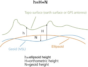
Q. - What is the meaning of Ellipsoidal Height?
A. - The ellipsoidal height is the vertical distance above the reference ellipsoid. It is measured, along the ellipsoidal normal, from the point to the ellipsoid surface.
Q. - What is the meaning of Orthometric Height?
A. - The orthometric - or equipotential - height is the vertical distance above the geoid. It is measured, along a line of force, from the point to the geoid surface.
Q. - What is the Geoid?
A. - The Geoid is the level of the Earth's surface. The geoid would have the shape of an oblate ellipsoid, centred on the Earth's centre of mass, if the Earth was of uniform density and the Earth's topography did not exist.
Q. - The results I obtain are different if I use a Digital Elevation Model referred to the ellipsoid or to the geoid. What is the best one to adopt?
A. - DEMs with ellipsoidal height have to be preferred in order to avoid errors related to the use of geoids, which differ depending on the specific geographic location. Vice versa the adoption of ellipsoidal heights ensure consistency with most of the current satellite systems, whose measurements and parameters are referred to earth center.
The scheme below shows the difference between geoidal or ellipsoidal references.
Q. - What are the Geoids used (and eventually subtracted) in the Digital Elevation Models imported by SARscape?
A. - The following two Geoids are used:
| - | The EGM96 Geoid for the SRTM-3 Digital Elevation Models. |
| - | The OSU91A Geoid for the RAMP Digital Elevation Model. |
Q. - What is the meaning of the Datum Shift?
A. - The Datum Shift parameters are used to convert the ellipsoid's origin into the Earth's centre.
Q. - Several SARscape panels (e.g Coregistration, Geocoding, Cartographic Transformations, etc.) enable different Resampling\Interpolation Methods. Is there any rule to choose the one which better performs with specific processing and/or input data?
A. - In general it should be noted that:
| - | The Nearest Neighbour considers only the closest pixel; it is suitable especially for under sampling classified data. |
| - | The Bilinear, the 3th Cubic Convolution and the 4th Cubic Convolution consider respectively 4, 8 and 16 surrounding pixels. In general the higher order interpolator provides better results, however in some cases the appearance of pixels with negative values has been reported on data resampled with the 4th Cubic Convolution. |
| - | The Sinc is the one which better approximate an ideal interpolator, it considers the 256 surrounding pixels, however it can introduce negative values especially when it get close to strong scatterers; for this reason attention should be paid when applying this resampling method to Intensity data. |
| - | The Optimal Resolution, which is specific for the Geocoding step, is typically applied to Single Look data in order to have an optimal result in terms of both radiometry and geometry preservation, especially when imaging hilly or mountainous zones. |
Q. - Why the Cartographic Grid Size of the output of geocoded product is 25 meter also when the input data (i.e. RADARSAT-2 fine beam) is better than 5 meter?
A. - The default geocoded output product grid size is set in the Preferences>General>Cartographic Grid Size. This value (i.e. 25 meters) will appear as default grid size in all processing panels where the output is a geocoded product (e.g. Basic>Geocoding and Radiometric Calibration, Interferometry>Phase to Height Conversion and Geocoding, Interferometry>Phase to Displacement Conversion and Geocoding and others). Of course the user can change this value also from the specific processing panel and in such case the new entered grid size will be used for the output product generation.
Q. - How do I have to enter the Geographic Co-ordinates: degrees, min. and sec. or rather decimal degrees?
A. - Geographic co-ordinates are inputted in decimal degrees. Co-ordinate decimal values must be entered using the dot (e.g. 29.30) and not the comma (e.g. 29,30) character.
Q. - Where and how are the Ground Control Points used in the SARscape processing chain?
A. - There are some functions, such as the Geocoding, the Interferogram Flattening, the "Geometry GCP" File in the PS and SBAS modules, and others where the GCP(s) are used to correct a scene location error in azimuth direction (i.e. wrong scene azimuth start time) and/or in range direction (i.e. wrong slant range distance). These corrections are not performed using an affine polynomial transformation, but the rigorous range-doppler approach; it means that one single and precise GCP is needed and sufficient for a proper execution of this correction process (in case more GCPs are used the same kind of correction will be executed, with the difference that the final shift parameters will come from the average calculated on all GCPs).
However there are errors in the data, which are not corrected when the above mentioned processes are performed; for instance if a wrong Pulse Repetition Frequency (PRF) is annotated in the original product, another tool must be adopted for the correction, which relies on the use of at least two GCPs that are eventually considered for the correction of the pixel spacing in azimuth direction. Also large orbital inaccuracies causing macroscopic scene rotations can not be corrected.
One practical thing which deserves to be mentioned is that, when the "nominal geolocation error" (i.e. error reported when an image is geocoded without using any GCP) is hard to be visually detected (e.g. 1 pixel or less), then it will be difficult to find a GCP so much accurate to correct such small error.
There is also another kind of GCP file, which is the "Orbital GCP" that is used during processes such as the "Refinement and Re-flattening" performed in several interferometric steps (Refinement and Re-flattening, PS, Stacking, etc.); in this case more GCP are needed to correct even the smallest orbital inaccuracies.
Q. - How SARscape products can be Interactively Edited?
A. - An editing functionality, which is specifically designed for the Interferometric Phase editing can be exploited for editing any other SARscape file.
Q. - How SARscape handles those Files, which have been Generated by ENVI own processing functions?
A. - In order to process any file by SARscape, the specific data must previously be imported using the relevant import functionality. Two possibilities are foreseen:
| - | The ENVI own file comes from a previous process within SARscape and its raster parameters have not changed; in this case the SARscape header (.sml) information can be recovered; the ENVI>SARscape Original import has to be used. |
| - | The ENVI own file does not come from a previous process within SARscape or its raster parameters have been changed due to the ENVI processing; the ENVI>ENVI Original import has to be used. |
Q. - What is the difference between using UPS or Stereographic Projection?
A. - The UPS is a gnomonic projection, which is specifically adopted for polar area representation; the projection plane is tangent to the surface of the sphere, the point of projection is at the sphere center. The Stereographic is an azimuthal orthomorphic projection, which is more suitable to be applied at different latitudes since its parameters can be adapted (Cartographic System>Cartographic Parameters) depending on the geographic location.
Q. - The Color Composite, which is generated with three SAR calibrated acquisitions using the relevant SARscape Tool, shows a dominant red color even if the acquisition assigned to the red channel should not be characterised by an overall higher backscatter. How can this behaviour be explained?
A. - The RGB composites are something which is often quite tricky from the interpretation point of view. Indeed, depending on how the original calibrated values are rescaled from the original floating format to the 24 bit (8 per colour channel) RGB tiff image, the appearance of the RGB representation changes.
In particular, in the "Generate Color Composite" tool, we have the possibility either to scale independently the three channels (default setting) or to apply a common scaling ("common scaling" or "mean in common scaling" flags) to the 3 layers; this last option is actually the best to preserve the original information. Nevertheless it often happens that we deal with backscatter changes, which are not only due to surface roughness local variation (e.g. flooded areas, vegetation growth, clear cuts, etc.), but also to the dielectric constant variation in most of the imaged area.
As an example, if we are looking at the backscatter changes due to a flood event, and we assume that the RGB is generated by assigning the "flooded acquisition/s" to the red and green channel, we often have a dominant yellow colour in most of the imaged area (where the surface roughness is not "flattened" by the floods, but the dielectric constant - and consequently the backscatter - increased due to the higher humidity in the soil, vegetation and also in the air...). Vice versa we'll have a dominant blue color where the terrain was actually covered by the flooding waters and thus the backscattered signal was approaching to zero in the red and green channels.
In order to solve this "visual interpretation" problem, once the RGB composite has been generated, we can manually stretch the histograms (independently for the three colour channels) until we get a grey tone, which means that there is not a dominant colour, in the areas where there was not change.
It remains that the real backscatter measure (temporal signature computed on the floating format calibrated products) should be adopted for a more reliable interpretation and change detection assessment, instead of using the general visual assessment that we can achieve by observing the RGB composite.
Q. - Is it possible to implement Data Masking?
A. - The approaches which are usually adopted for masking
Q. - Processing functionalities - and more in general any software command - are disabled whether a processing step is running; is there any way to Interact with the Program when Another Processing is Going On?
A. - It is possible to operate any functionality, from either ENVI or SARscape, if the SARscape processing is executed in batch mode instead of being launched directly from the panel "start" button. It is important to note that, when more batch processes have to be executed in parallel on the same machine, the working directory must be set on a different location for each batch sequence.
Q. - It is not so easy to choose the right File Names (extensions) when preparing a sequential Batch Processing Chain?
A. - This process typically becomes easier when users become more familiar with SARscape products and related naming conventions. Useful indications about the output naming extensions can be gained by reading the Nomenclature section.
Q. - We try to derive Forest Variables from Coherence data. Clear-cut areas have higher coherence than areas with vegetation and trees. However, we see that coherence is influenced also by topography and backscatter intensity. Is there a way to reduce the coherence dependency from topography?
A. - The spectral shift filter, which is normally set as default, is one of the processing parameters useful for this purpose; it is performed during the Interferogram Generation as follows: when the "Coregistration with DEM" flag is checked, the filtering is adapted to the local slope; vice versa when the "Coregistration with DEM" flag is not checked, a flat earth is considered without any local slope dependency.
Moreover the slope dependency can be reduced by checking the Remove Residual Phase Frequency (default parameter); this setting is implemented during the execution of the "Adaptive Filter and Coherence Generation" step.
Finally, for a proper use of the coherence to derive (or model) forest related parameters, a useful input is the Local Incidence Angle map (_lia). This is generated, when the relevant flag is checked, during the geocoding step; the geocoded Local Incidence Angle map can eventually be converted in slant range geometry by using the Map to Slant Range Image Transformation tool.
Q. - Is there any reference manual to introduce Marine Application using SAR data?
A. - The SAR Marine User's Manual is to lay out, for a wide range of users, the types of information that may be obtained from SAR images of the ocean, and methods of analyzing these data. It is intended for non-expert - but scientifically literate workers - who wish to use SAR data in their studies.