|
<< Click to Display Table of Contents >> Interferometry - Stereo Radargrammetry - 3 - Shift to Height Conversion and Geocoding |
  
|
|
<< Click to Display Table of Contents >> Interferometry - Stereo Radargrammetry - 3 - Shift to Height Conversion and Geocoding |
|
Purpose
The absolute calibrated shift is re-combined with the synthetic shift and it is converted to height and geocoded into a map projection. This step is performed in a similar way as in the geocoding procedure (Basic module), by considering the Range-Doppler approach and the related geodetic and cartographic transforms. The fundamental difference with the geocoding step is that the Range-Doppler equations are applied simultaneously to the two antennae, making it possible to obtain not only the height of each pixel, but also its location (Easting, Northing) in a given cartographic and geodetic reference system.
As result of this step also the coherence image is geocoded.
Technical Note
The shift-to-height conversion is performed with a forward transformation. The calculated X, Y, Z Cartesian coordinates (and thereafter map coordinates) are transformed into the coordinates of the output DEM exclusively using a Nearest Neighbor approach.
Two files are generated in this step, beside the Digital Elevation Model and the geocoded coherence image, for a further use in the data mosaicing. They are:
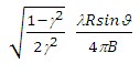
- Precision, which is derived from parameters such as cross-correlation, baseline and wavelength. It provides an estimate (i.e. standard deviation value) of the measurement precision. The higher this value the lower the measurement precision. The formula used for the precision calculation is:
- Resolution, which represents the pixel resolution in ground range, that is:
pixel spacing slant range
sinϑ
where γ is the intensity cross-correlation, λ is the wavelength, R is the slant range distance, ϑ is the local incidence angle.
- Spatial Wavelet Size
The Height Wavelet size, expressed in meters, define what is kept of the residual topography estimated from processing data resolution till the specified resolution value. It removes the low pass distortion under the set resolution value by using wavelet decomposition.
- Data Interpolation is intended to assign a specific value to the dummy (NaN) pixels. The "Relax Interpolation" model is represented by a soft surface, which is adapted to the dummy surrounding area. The algorithm, which is based on the solution of the heat transfer equation (Poisson equation), uses known height values to reconstruct at the best the unknown topography; for this reason it is optimally suited to interpolate small zones, especially where abrupt morphological changes (i.e. steep slopes) are not present.
- Generate Shape format allows representing the DEM as a point cloud. This procedure is intended to preserve the actual pixel value without applying any interpolation, which is the case of the raster output. This format is the one to use as input for the Point Cloud DEM Fusion and for the Point Gridding. It can happen that the .shp and the .dbf become very large when there are a lot of valid points.
Input Files
Coherence file
Name of the coherence image (_cc). This file is mandatory.
Input Range Shift File
Name of the Shift file in range direction (_dr). This file is mandatory.
Range Synthetic Shift File
Name of the synthetic shift file in range direction (_rg_sint). This file is mandatory.
Reference File
File name of the multi-looked Reference Intensity data (_pwr). This file is mandatory.
Secondary File
File name of the multi-looked coregistered Secondary Intensity data (_pwr). This file is mandatory.
Output Root Name
Name of the output root. This file is optional.
DEM/Cartographic System
Output Projection
The following parameters are compulsory to define the Cartographic System:
State
Definition of the country or general projection systems.
Projection
Definition of the projection system of the selected State. In case that a general projection system is selected in State, the Projection is automatically set.
Ellipsoid
Definition of the ellipsoid. This is chosen according to the selected State and Projection.
Hemisphere
Definition of the hemisphere. This is chosen according to the selected State and Projection.
Zone
Definition of the zone. This is chosen according to the selected State and Projection.
Datum Shift Parameters
Definition of the datum shift parameters. These are chosen according to the selected State and Projection.
Cartographic Parameters
The reference parameters for some projection systems (e.g. Stereographic, Polar Stereographic, Gnomonic, Mercator, Miller, Albers, etc.) can be set.
Parameters - Principal Parameters
Cross Correlation Threshold
If the correlation value is below this threshold, then the window is not used for the shift estimate.
Spatial Wavelet Size
The Height Wavelet size, expressed in meters, define what is kept of the residual topography estimated from processing data resolution till the specified resolution value. It removes the low pass distortion under the set resolution value by using wavelet decomposition.
Generate Raster format
By setting this flag the DEM is generated in raster format.
Generate Shape format
By setting this flag the DEM is generated in vector (.shp) format.
Generate Las format
By setting this flag the DEM is generated in Las format.
Output Type
Allows the use to choose between an output DEM with ellipsoidal heights (default) or heights over the geoid. The geoid type can be chosen in the next flag.
Geoid Type
By setting this flag it is possible to choose the geoid model (default: EGM96) used for geodetic heights in case "Ellipsoidal and Geoidal" is set in the previous flag.
Grid Size
The grid size of the output data must be defined; the default unit of measure is meters.
Note that - for the Geographic projection - if values higher than 0.2 are entered they will be considered as metric units and then automatically, and roughly, converted from meters to degrees; if values lower than 0.2 are entered they will be considered as degree and used as such without any conversion.
Different grid size, in Easting (X) and Northing (Y) direction, can be specified.
Mean Window Size
The mean filtering of the output height image is carried out. The window filter size must be specified. If zero is entered, the mean filtering is not applied. This filter is applied after the execution of the interpolation steps. The mean filtering is performed only on the Digital Elevation Model output.
Interpolation Window Size
The dummy values in the output file are interpolated. The interpolated value is the average of the valid values in a window of the size specified. If zero is entered, the interpolation is not applied; it is suggested to avoid setting this value to zero (see Technical Note).
Relax Interpolation
By setting this flag the relax interpolation is carried out. This interpolation is applied only to the Digital Elevation Model output.
Dummy Removal
By setting this flag the output geocoded files will be automatically resized in order to remove the dummy area exceeding the frame border.
Parameters - Global
It brings to the general section of the Preferences parameters. Any modified value will be used and stored for further processing sessions.
Parameters - Geocoding
It brings to the geocoding section of the Preferences parameters. Any modified value will be used and stored for further processing sessions.
Parameters - Other Parameters
It brings to the general section of the Preferences parameters. Any modified value will be used and stored for further processing sessions.
Output Files
Output Root Name
Name of the output root. It is mandatory.
_dem
Digital Elevation Model with the associated header files (.sml, .hdr).
_dem.shp
Digital Elevation Model in shape format and associated header files (.sml, .hdr).
_cc_geo
Geocoded coherence with the associated header files (.sml, .hdr).
_precision
Estimate of the data quality with the associated header files (.sml, .hdr). This file is used during the Digital Elevation Model mosaicing (Tools).
_resolution
Spatial resolution based on the local incidence angle with the associated header files (.sml, .hdr). This file is used during the Digital Elevation Model mosaicing (Tools).
Details specific to the Units of Measure and Nomenclature of the output products can be found in the Data Format section.
General Functions
Exec
The processing step is executed.
Store Batch
The processing step is stored in the batch list. The Batch Browser button allows to load the batch processing list.
Close
The window will be closed.
Help
Specific help document section.
Specific Function(s)
None.
Task, SARscapeBatch object, SARscapeBatch script example
References Holecz F., J. Moreira, P. Pasquali, S. Voigt, E. Meier, D. Nuesch: "Height Model Generation, Automatic Geocoding and Mosaicing using Airborne AeS-1 InSAR Data". Proceedings of IGARSS'97 Symposium, 1997. W. Göblirsch and P. Pasquali: "Algorithms for calculation of digital surface models from the unwrapped interferometric phase". Proceedings of IGARSS 1996, pp. 656–658.