|
<< Click to Display Table of Contents >> Interferometry - MAI - MAI Phase to Displacement Conversion and Geocoding |
  
|
|
<< Click to Display Table of Contents >> Interferometry - MAI - MAI Phase to Displacement Conversion and Geocoding |
|
Purpose
The absolute refined phases (_upha, _mai_upha) values are converted to displacement and directly geocoded into a map projection. This step is performed in a similar way as in the geocoding procedure (Basic module), by considering the Range-Doppler approach and the related geodetic and cartographic transforms. The fundamental difference with the geocoding step is that the Range-Doppler equations are applied simultaneously to the two antennae, making it possible to obtain not only the displacement of each pixel, but also its location (Easting, Northing) in a given cartographic and geodetic reference system.
As result of this step also the coherence image is geocoded.
Technical Note
Each 2π cycle ( interferometric fringe) of differential phase corresponds to half wavelength of displacement along the Slant Range direction (SAR viewing direction), while for the MAI, the phase is converted in displacement along the satellite flying direction by a factor depending on the antennae sub-aperture distance. It is possible to specify any vector (i.e direction and inclination) where the measured slant range displacement (from _upha) - component of the deformation in the satellite viewing direction - will be projected. Hence this vector represents the re-projection of the slant range deformation component onto a direction on the ground which is known a-priori and specified by the user (i.e. "vertical" in case of subsidence; "slope" in case of landslides; "custom" in any other case).
The output map shows displacement magnitude in meters:
- Slant Range Displacement - Positive sign if the movement corresponds to a decrease of the sensor-to-target slant range distance (Secondary respect to Reference acquisition);
- Azimuth displacement - Positive sign if the movement increases along the satellite flying direction;
- Displacement Custom Direction - Positive sign corresponds to movement in the user defined direction (Secondary respect to Reference acquisition). It can be applied only to the standard interferometric phase component.
Displacement Custom Direction
Direction and inclination of the displacement vector can be specified. As an example an "azimuth angle" of 45° means that the displacement is oriented North 45° East and the movement is expected Northeastward; while an "azimuth angle" of 225° means that the displacement is always oriented North 45° East, but the movement is expected Southwestward. Positive inclination angles indicate upward movement; negative inclination angles indicate downward movement.
Precision
This output product, which is derived from parameters such as coherence and wavelength, provides an estimate (i.e. standard deviation value) of the measurement precision. The higher this value the lower the measurement precision. The formula used for the precision calculation is:

where γ is the interferometric coherence.
It is important to outline that the Refinement and Re-flattening step must have been performed previously
Input Files
MAI Coherence File
File name of the coherence (_mai_cc). This file is mandatory.
Coherence File
File name of the coherence (_cc). This file is mandatory.
MAI Unwrapped Phase file
File name of the reflattened unwrapped phase (_mai_upha). This file is mandatory.
Unwrapped Phase file
File name of the reflattened unwrapped phase (_upha). This file is mandatory.
DEM/Cartographic System
Digital Elevation Model file
Name of the Digital Elevation Model file. This should be referred to the ellipsoid. This file is optional. In case it is omitted, the ellipsoidal height and the relevant cartographic reference system, must be entered.
Output Projection
In case that the Digital Elevation Model is not used, the following parameters are compulsory to define the Cartographic System:
State
Definition of the country or general projection systems.
Projection
Definition of the projection system of the selected State. In case that a general projection system is selected in State, the Projection is automatically set.
Ellipsoid
Definition of the ellipsoid. This is chosen according to the selected State and Projection.
Hemisphere
Definition of the hemisphere. This is chosen according to the selected State and Projection.
Zone
Definition of the zone. This is chosen according to the selected State and Projection.
Datum Shift Parameters
Definition of the datum shift parameters. These are chosen according to the selected State and Projection.
Cartographic Parameters
The reference parameters for some projection systems (e.g. Stereographic, Polar Stereographic, Gnomonic, Mercator, Miller, Albers, etc.) can be set.
Parameters - Principal Parameters
Product Coherence Threshold
Pixels with coherence values smaller than this threshold will be set to dummy (NaN) in the final products.
Vertical Displacement
By setting this flag the map showing the displacement values projected on the vertical direction is generated among the output products.
Slope Displacement
By setting this flag the map showing the displacement values projected along the maximum slope is generated among the output products.
Displacement Custom Direction
By setting this flag any vector can be specified, in terms of azimuth (Azimuth Angle, measured in degrees from the North - clockwise direction) and inclination (Inclination Angle, measured in degrees from the horizontal plane). The map showing the displacement values projected on the specified direction is generated among the output products.
X Dimension (m)
The grid size of the output data in Easting (X) must be defined; the default unit of measure is meters.
Note that - for the Geographic projection - if values higher than 0.2 are entered they will be considered as metric units and then automatically, and roughly, converted from meters to degrees; if values lower than 0.2 are entered they will be considered as degree and used as such without any conversion.
Y Dimension (m)
The grid size of the output data in Northing (Y) must be defined; the default unit of measure is meters.
Note that - for the Geographic projection - if values higher than 0.2 are entered they will be considered as metric units and then automatically, and roughly, converted from meters to degrees; if values lower than 0.2 are entered they will be considered as degree and used as such without any conversion.
Interpolation Window Size
By setting this flag the dummy values in the output file are interpolated. The interpolated value is the average of the valid values in a window of the size selected.
Dummy Removal
By setting this flag the output geocoded files will be automatically resized in order to remove the dummy area exceeding the frame border.
Parameters - Global
It brings to the general section of the Preferences parameters. Any modified value will be used and stored for further processing sessions.
Parameters - Geocoding
It brings to the geocoding section of the Preferences parameters. Any modified value will be used and stored for further processing sessions.
Parameters - Displacement Projection
Generate Line Of Sight
by setting this flag the displacement in line of sight and satellite flying direction as measured by the satellite in generated.
Vertical Displacement
By setting this flag the map showing the displacement values projected on the vertical direction is generated among the output products.
Slope Displacement
By setting this flag the map showing the displacement values projected along the maximum slope is generated among the output products.
Displacement Custom Direction
By setting this flag any vector can be specified, in terms of azimuth (Azimuth Angle, measured in degrees from the North - clockwise direction) and inclination (Inclination Angle, measured in degrees from the horizontal plane). The map showing the displacement values projected on the specified direction is generated among the output products.
Parameters - Other Parameters
It brings to the general section of the Preferences parameters. Any modified value will be used and stored for further processing sessions.
Output Files
Output Root Name
Name of the output root. It is mandatory.
_dem
Input Digital Elevation Model resampled onto the specified cartographic system and grid size, with the associated header files (.sml, .hdr). Its areal extent is the same as the output SAR products.
_disp_cc_geo
Geocoded coherence in range direction with the associated header files (.sml, .hdr).
_mai_disp_cc_geo
Geocoded coherence in azimuth direction with the associated header files (.sml, .hdr).
_ADF
Maximum slope direction values, with the associated header files (.sml, .hdr).
_IDF
Maximum slope inclination values, with the associated header files (.sml, .hdr).
_SD
Displacement values along the maximum slope direction, with the associated header files (.sml, .hdr).
_UD
Displacement values in the direction specified as azimuth and inclination degrees (i.e. custom direction), with the associated header files (.sml, .hdr).
_VD
Vertical displacement values, with the associated header files (.sml, .hdr).
_disp
Slant Range (satellite view direction) displacement values, with the associated header files (.sml, .hdr).
_mai_disp
Azimuth (satellite flying direction) displacement values, with the associated header files (.sml, .hdr).
_disp_precision
Estimate of the data quality in range with the associated header files (.sml, .hdr). This file is generated only if the coherence file is entered as input.
_mai_disp_precision
Estimate of the data quality in azimuth with the associated header files (.sml, .hdr). This file is generated only if the coherence file is entered as input.
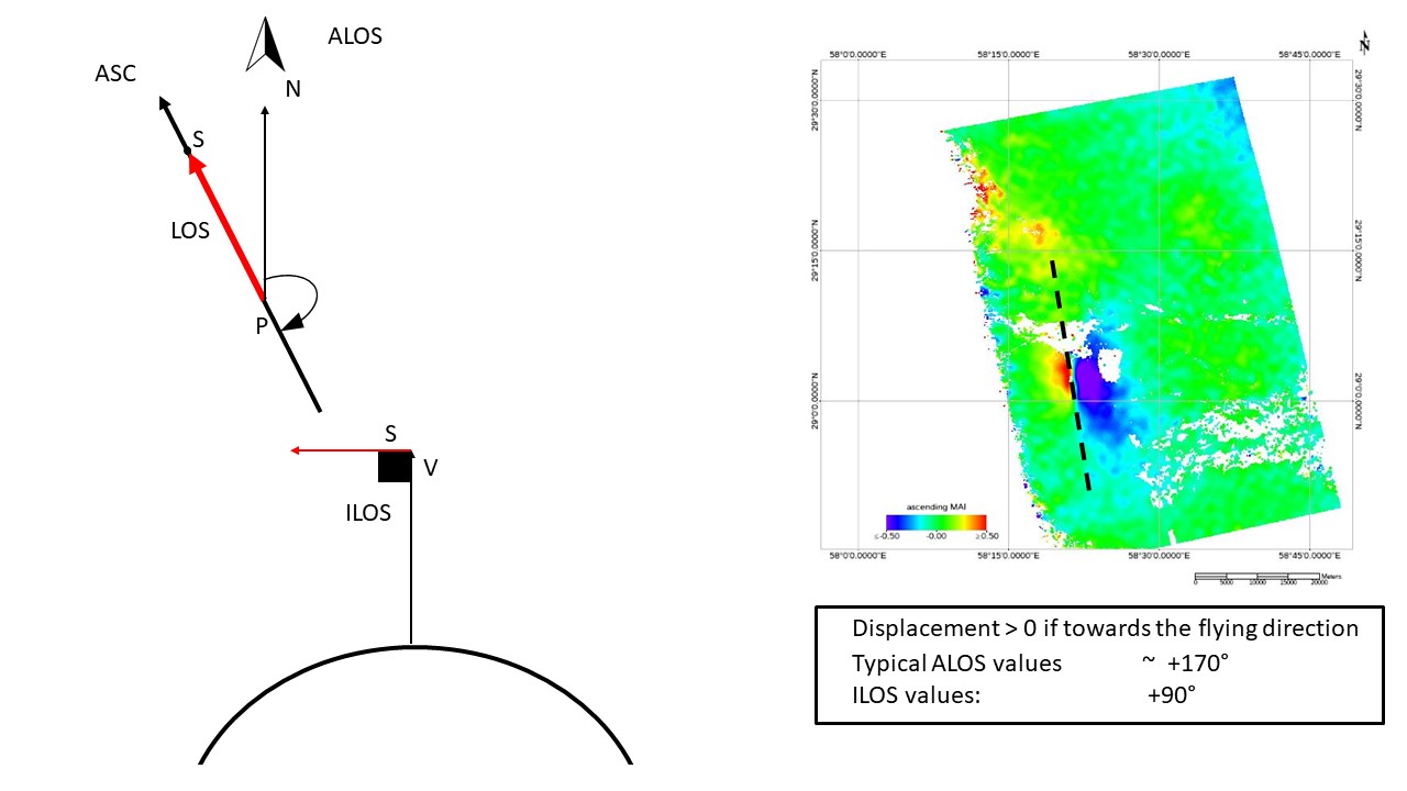
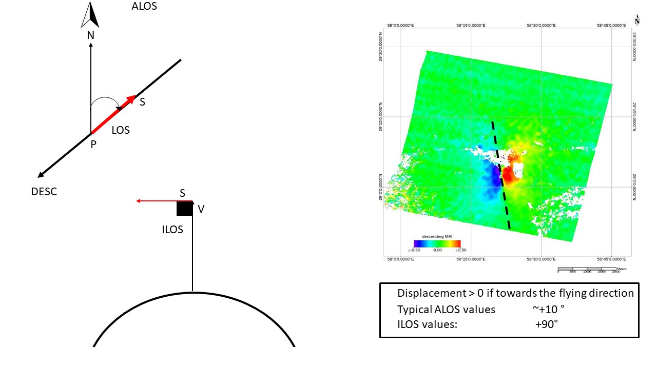
_disp_ALOS
Azimuth Line of Sight with the associated header files (.sml, .hdr). Positive angles are measured clockwise from the North; negative angles are measured counterclockwise from the North.
_mai_ disp_ALOS
Satellite flying direction with the associated header files (.sml, .hdr). Positive angles are measured clockwise from the North; negative angles are measured counterclockwise from the North.
_disp_ILOS
Incidence angle of the Line of Sight with the associated header files (.sml, .hdr). The angle is measured between the Line Of Sight and the vertical on the ellipsoid (flat earth).
_mai_disp_ILOS
Incidence angle for the Satellite flying direction with the associated header files (.sml, .hdr). The angle is measured between the Flying Direction and the vertical on the ellipsoid (flat earth).
Details specific to the Units of Measure and Nomenclature of the output products can be found in the Data Format section.
General Functions
Exec
The processing step is executed.
Store Batch
The processing step is stored in the batch list. The Batch Browser button allows to load the batch processing list.
Close
The window will be closed.
Help
Specific help document section.
Specific Function(s)
None.
Task, SARscapeBatch object, SARscapeBatch script example
References None.