|
<< Click to Display Table of Contents >> Basic Module - Intensity Processing - Geocoding - Layover and Shadow Mask Generation |
  
|
|
<< Click to Display Table of Contents >> Basic Module - Intensity Processing - Geocoding - Layover and Shadow Mask Generation |
|
Purpose
This functionality generates the layover and shadow mask and optionally the local incidence angle map. The products can be provided in both original slant range geometry and geocoded geometry.
Technical Note
The Local Incidence Angle represents the angle between the normal to the backscattering element and the incoming radiation.
The Layover and shadow represent a validity measurement mask. The Layover and Shadow effects are influenced by geometry in range configuration and by topography. For this reason, the projection of individual points onto the slant range plane varies with respect to the incidence angle and the slope.
Foreshortening occurs when the radar beam reaches elevated areas (e.g. a mountain or buildings). With an increasing (horizontal) distance, the slant range between sensor and target decreases.
The layover effect (active, b-a), which characterizes those slopes whose inclination is steeper than the radar look angle, extends far beyond than the slope itself. It occurs when the radar beam reaches the top of a relief (b) before it reaches the base (a). The return signal from the top of the feature will be received before the signal from the bottom.
The zone affected by the layover corresponds to that area where the sensor-target distance decreases (i.e. the top of the slope is imaged before than its foot), while it should increase assuming a "flat earth". For this reason, the beginning of the layover area is before the foot of the slope and its end is after the top of the slope.
See the figure on the left for the definition of the layover classes.
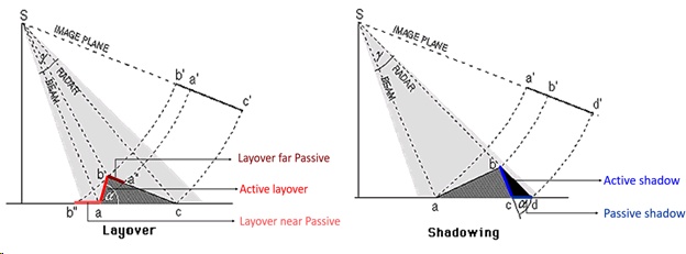
Shadow effect occurs when the radar beam is not able to illuminate a slope (active, bc) or the ground surface behind it close enough to be influenced by the slope geometry (passive, cd). See the figure on the right for the definition of the shadow classes.
Where the imaged area is not affected by either layover or shadow, the "Layover/Shadow" mask shows the Local Incidence Angle values in discrete intervals.
Note: SAR images in PFA format are not supported as input.
Input Files
Input file
Input file (_pwr, _gr, _slc, _fil) in original slant range geometry to be used. This file is mandatory.
Optional Files
Geometry GCP file
Either a previously created Ground Control Point file (.xml) is loaded (Load GCP file) or the interface to create a new Ground Control Point file is automatically loaded (Create GCP file, refer to the "Tools>Generate Ground Control Point" for details). This file is optional.
Geo Output Reference File
Name of the file in geocoded geometry used as reference. The geocoded products keep the same geocoded reference image size and sampling. The grid size of the reference file should be comparable with the sampling of the Input file in slant range original geometry, to obtain correct products. This file is optional. Alternatively, the geocoded products coverage is estimated from the original slant range geometry corners approximate ground location itself and the sampling is defined by the X and Y Dimension (m).
DEM/Cartographic System
DEM File
Digital Elevation Model (DEM) file name. This should be referred to the ellipsoid. In case a list of input files is entered, the DEM must cover the whole imaged area. This file is mandatory.
Output Projection
In case that the Digital Elevation Model is not used, it is mandatory to define the Cartographic System.
The Reset icon allows to reset the coordinate system field.
To use the same coordinate system as of another dataset, click the From Dataset button and select the source dataset.
To apply the same Coordinate System of the current selected layer, click the From Current View button.
Reference Height
In case that Digital Elevation Model is not used, a constant ellipsoidal height must be provided. The default reference height is 0.
Parameters - Principal Parameters
Original Geometry Products
By setting this flag the program generates the products in original slant range geometry.
Geocoded Geometry Products
By setting this flag the program generates the products in geocoded geometry. The ground products coverage is defined from the Geo Output Reference File ground coverage or alternatively from the original slant range geometry corners approximate ground location itself. The ground products sampling is defined from the Geo Output Reference File sampling or alternatively from the X and Y Dimension (m). The grid size should be comparable with the Input file in slant range original geometry sampling, to obtain correct products.
Local Incidence Angle
By setting this flag the program generates the Local Incidence Angle as well.
X Dimension (m)
The Easting (X) grid size of the output data must be defined when the Geo Output Reference File is not; the default unit of measure is meters. The grid size should be comparable with the Input file in slant range original geometry sampling, to obtain correct products.
Note that for the Geographic projection, if values higher than 0.2 are entered they will be considered as metric units and then automatically, and roughly, converted from meters to degrees; if values lower than 0.2 are entered they will be considered as degree and used as such without any conversion.
Y Dimension (m)
The Northing (Y) grid size of the output data must be defined when the Geo Output Reference File is not; the default unit of measure is meters. The grid size should be comparable with the Input file in slant range original geometry sampling, to obtain correct products.
Note that for the Geographic projection, if values higher than 0.2 are entered they will be considered as metric units and then automatically, and roughly, converted from meters to degrees; if values lower than 0.2 are entered they will be considered as degree and used as such without any conversion.
Parameters - Global
It brings to the general section of the Preferences parameters. Any modified value will be used and stored for further processing sessions.
Parameters - Geocoding
It brings to the geocoding section of the Preferences parameters. Any modified value will be used and stored for further processing sessions.
Parameters - Other Parameters
It brings to the general section of the Preferences parameters. Any modified value will be used and stored for further processing sessions.
Output Files
Output Root Name
Name of the output root. This file is mandatory. It is used as root name to define all the output products:
•_geo_lia, Local Incidence Angle in geocoded geometry.
•_geo_ls_mask, Layover and Shadow Mask classified mask in geocoded geometry.
•_srlia, Local Incidence Angle in original slant range geometry.
•_ ls_mask, Layover and Shadow Mask classified mask in original slant range geometry.
Details specific to the Units of Measure and Nomenclature of the output products can be found in the Data Format section.
General Functions
Store Batch
The processing step is stored in the batch list. The Batch Browser button allows to load the batch processing list.
Exec
The processing step is executed.
Close
The window will be closed.
Help
Specific help document section.
Task, SARscapeBatch object, SARscapeBatch script example
References Walter G. Kropatsch and Dieter Strobl: "The Generation of SAR Layover and Shadow Maps from Digital Elevation Models". IEEE Transactions on Image Processing, Vol. 28, No. 1, January 1990.