|
<< Click to Display Table of Contents >> Interferometry -MAI - MAI Interferometric Processing |
  
|
|
<< Click to Display Table of Contents >> Interferometry -MAI - MAI Interferometric Processing |
|
Purpose
This functionality enables to execute, in a single iteration, the following processing sequence:
–Interferogram Generation and Flattening.
–Adaptive Filter and Coherence Generation.
It is important to point out that, in case ENVISAT-ERS pairs are processed, the "Coregistration with DEM” flag must be checked.
Please, consider that Sentinel-1 data are not supported for MAI processing.
Technical Note
Details specific to each step implemented here are described in the relevant section of the reference guide. We recommend to read it carefully.
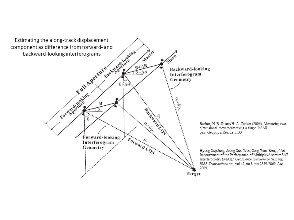
MAI (Multi Aperture Interferometry)
It activates the decomposition of the original doppler bandwidth, in the Reference and Secondary data, into smaller portions of the full spectrum. The result of this process is the generation of an additional differential interferogram (_mai_fint), which represents the displacement observed in azimuth direction.
The input "factor" is aimed at defining how many pieces the original (full) doppler spectrum must be subdivided in: the higher the "factor" the more the pieces, which means noisier split interferograms (due to the limited doppler bandwidth exploited) but higher sensitivity to the azimuth displacement. It must be noted that in any case the sensitivity to the displacement is much coarser than in range direction. The larger the MAI factor, the higher the separation between the sub-apertures, hence the displacement sensitivity along the azimuth direction (satellite flight direction) while the band spectrum becomes smaller along with the SNR.
This functionality has been currently tested on ENVISAT ASAR, ALOS PALSAR and ERS data; the program can fail in case other sensors are used. The program requires data pairs characterized by a small doppler difference; large doppler variations can cause program failures.
Note: slc_list and burst mode images are not supported as input data.
Input Files
Input Reference file
File name of the Reference data (_slc). This file is mandatory.
Input Secondary file
File name of the Secondary data (_slc). This file is mandatory.
Optional Files
Geometry GCP file
Either a previously created Ground Control Point file (.xml) is loaded (Load GCP File) or the interface to create a new Ground Control Point file is automatically loaded (Create GCP File, refer to the "Tools>Generate Ground Control Point" for details). This file is optional.
DEM/Cartographic System
Digital Elevation Model file
Digital Elevation Model file name. This should be referred to the ellipsoid. In case a list of input files is entered, the DEM must cover the whole imaged area. This file is optional.
Output Projection
In case that the Digital Elevation Model is not used, it is mandatory to define the Cartographic System.
To use the same coordinate system as another dataset, click the Import from Existing Dataset button and select the source dataset.
To apply the same Coordinate System of the current selected layer
The reset icon allows to reset the coordinate system field.
.
Parameters - Principal Parameters
Range Looks
Number of looks in range.
Azimuth Looks
Number of looks in azimuth.
Grid Size for Suggested Looks
The grid size, in meters, used to tune range and azimuth looks. If the other parameters are manually set, the grid size will not imply a change in their values.
Generate Flattening Interferogram
By setting this flag, the Flattened interferogram is generated. If the MAI factor is set to values different than 1 the original doppler bandwith will be decomposed, resulting in outputs corresponding to both the lowermost and uppermost portion of the doppler spectrum.
Generate Filtering and Coherence
By setting this flag, the Filtered interferogram is generated. This file is generated only if the Adaptive Filter flag is selected. If the MAI factor is set to values different than 1 the original doppler bandwith will be decomposed, resulting in FINT outputs corresponding to both the lowermost and uppermost portion of the doppler spectrum.
Generate Unwrapping
By setting this flag, the Unwrapped phase is generated.
By setting this flag, the input Digital Elevation Model is used in the coregistration process.
Unwrapping Method Type
The choice is given between the following unwrapping methods:
•Region Growing, the Region Growing unwrapping method is used;
•Minimum Cost Flow, the Minimum Cost Flow (square grid) unwrapping method is used;
•Delaunay MCF, the Minimum Cost Flow (triangular grid) unwrapping method is used;
Refer to Phase Unwrapping for further information.
Unwrapping Decomposition Level
The number of under sampling levels to be applied to the complex interferogram before performing the phase unwrapping can be specified. Refer to Phase Unwrapping, Technical Notes for further information.
Unwrapping Coherence Threshold
Pixels with coherence values smaller than this threshold are not unwrapped.
Filtering Method
The choice is given to execute the "Interferogram Filter and Coherence Generation" using the following filtering methods according to the default values of the filtering section of the Preferences parameters:
•Goldstein
•Boxcar
•Adaptive
•Adaptive Non Local InSAR
Refer to Adaptive Filter and Coherence Generation for further information.
Coherence from Fint
By setting this flag, the coherence is computed using the filtered interferogram (_fint) instead of the unfiltered one (_dint).
MAI Factor
Enter the number of pieces the original (full) doppler spectrum must be subdivided in.
Parameters - Global
It brings to the general section of the Preferences parameters. Any modified value will be used and stored for further processing sessions.
Parameters - Interferogram
It brings to the interferometry section of the Preferences parameters. Any modified value will be used and stored for further processing sessions.
Parameters - Flattening
It brings to the flattening section of the Preferences parameters. Any modified value will be used and stored for further processing sessions.
Parameters - Filtering
It brings to the adaptive filter section of the Preferences parameters. Any modified value will be used and stored for further processing sessions.
Parameters - Phase Unwrapping
It brings to the phase unwrapping parameters section of the Preferences parameters. Any modified value will be used and stored for further processing sessions.
Parameters - Coregistration
It brings to the coregistration section of the Preferences parameters. Any modified value will be used and stored for further processing sessions.
Parameters - Other Parameters
It brings to the general section of the Preferences parameters. Any modified value will be used and stored for further processing sessions.
Output Files
Output Root Name
Name of the output root. This file is mandatory.
_int
Interferogram with the associated header files (.sml, .hdr).
_par
ASCII file containing the coregistration shift parameters in range and azimuth.
_pwr
Multi-looked Reference (_Reference) and Secondary (_Secondary) image with the associated header files (.sml, .hdr).
_orb.sml
Xml file containing the scene orbital parameters.
_orbit_off.shp
Shape file with the points used to estimate the orbit - and DEM in case the "Coregistration with DEM" flag is checked - based shift. This file contains the following information:
| - | Pixel position in range direction (Range), in original pixel units. |
| - | Pixel position in azimuth direction (Azimuth), in original pixel units. |
| - | Shift measured in range direction (Dr), in original pixel units. |
| - | Shift measured in azimuth direction (Da), in original pixel units. |
| - | Calculated polynomial fitted shift in range direction (Drfit), in original pixel units. |
| - | Calculated polynomial fitted shift in azimuth direction (Dafit), in original pixel units. |
The file is multilooked (i.e. Azimuth and Range looks) as specified in the Input Parameters.
_winCC_off.shp
Shape file with the points used to estimate the cross correlation based shift from the Intensity data. In addition to the information provided by the "_orbit_off.shp" file, which are updated on the basis of the cross correlation estimate, this file contains also the following information (provided that the "Coregistration with DEM" flag is checked):
| - | Residual shift in range direction (DrResidual), in original pixel units. This is the difference with respect to the previously measured (orbit_off.shp) shift. |
| - | Residual shift in azimuth direction (DaResidual), in original pixel units. This is the difference with respect to the previously measured (orbit_off.shp) shift. |
| - | Calculated polynomial fitted residual shift in range direction (DrFitRes), in original pixel units. This is the difference with respect to the previously fitted (orbit_off.shp) shift. |
| - | Calculated polynomial fitted residual shift in azimuth direction (DaFitRes), in original pixel units. This is the difference with respect to the previously fitted (orbit_off.shp) shift. |
_winCoh_off.shp - It is generated only when Single Look Complex data are used as input
Shape file with the points used to estimate the coherence based shift. The information provided in the "_winCC_off.shp" are updated by means the coherence based estimate. This file contains also the following additional information:
| - | Signal to Noise Ratio (SNR), which is a linear dimensionless value. |
| - | Coherence value. It is dimensionless and it can vary from 0 to 1. |
The file is generated using the multilooking factors (i.e. Azimuth and Range looks) specified in the Input Parameters.
_dint
Flattened interferogram with the associated header files (.sml, .hdr).
_sint
Synthetic phase with the associated header files (.sml, .hdr).
_srdem
Digital Elevation Model, in slant range geometry, with the associated header files (.sml, .hdr).
_fint
Filtered interferogram with the associated header files (.sml, .hdr). This file is generated only if the Adaptive Filter flag is selected.
_mai_fint
Filtered interferogram, corresponding to the difference between lowermost (_part2_fint) and uppermost (_part1_fint) portions of the doppler spectrum, with the associated header files (.sml, .hdr). This file is generated only if the MAI functionality is activated (refer to the "Technical Note").
_cc
Estimated coherence in range direction with the associated header files (.sml, .hdr). This file is generated only if the Coherence Generation flag is selected.
_mai_cc
Estimated coherence in azimuth direction with the associated header files (.sml, .hdr). This file is generated only if the Coherence Generation flag is selected.
_upha
Unwrapped phase in range direction with the associated header files (.sml, .hdr).
_mai_upha
Unwrapped phase in azimuth direction with the associated header files (.sml, .hdr).
Details specific to the Units of Measure and Nomenclature of the output products can be found in the Data Format section.
General Functions
Exec
The processing step is executed.
Store Batch
The processing step is stored in the batch list. The Batch Browser button allows to load the batch processing list.
Close
The window will be closed.
Help
Specific help document section.
Specific Function(s)
None.
Task, SARscapeBatch object, SARscapeBatch script example
References Consult the reference guide specific to each processing step.