|
<< Click to Display Table of Contents >> Basic Module - Feature Extraction - Multitemporal Coherence |
  
|
|
<< Click to Display Table of Contents >> Basic Module - Feature Extraction - Multitemporal Coherence |
|
Purpose
Single-date and multi-temporal features based on first order statistics Intensity image(s) or interferometric image pairs can be derived from SAR data. These features enable, depending upon the targeted product, to detect and extract structures or temporal changes, which can be additionally used for segmentation and/or classification purposes. This multitemporal approach allows to compute coherence using several input images.
Technical Note
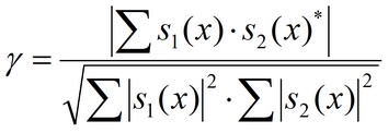
Given two coregistered complex SAR images (S1 and S2), one calculates the interferometric coherence (γ) as a ratio between coherent and incoherent summations. Note that the observed coherence - which ranges between 0 and 1 - is, in primis, a function of systemic spatial de-correlation, the additive noise, and the scene de-correlation that takes place between the two acquisitions.
The estimated coherence - which ranges between 0 and 1 - is function of:
| - | Systemic spatial de-correlation (i.e. the additive noise). |
| - | Temporal de-correlation between Reference and Secondary acquisitions. |
The coherence product has essentially a twofold purpose:
| - | To determine the quality of the measurement (i.e. interferometric phase). As a rule of thumb, InSAR pairs with low coherence should not be used to derive reliable phase related measurements. |
| - | To extract thematic information relevant to the ground features properties and their temporal changes. This information is enhanced when coupled with the backscattering coefficient (σo) of the Reference and Secondary Intensity data. |
As a general rule it can be assumed that the coherence decreases with increasing Reference-Secondary acquisition time distance. The relationship between the coherence (γ) and the Signal to Noise Ratio (SNR) is:
SNR = γ2/1-γ2
In case the two images are very much different in terms of areal coverage, the smallest one should be used as "Input Reference file" in order to avoid the coregistration windows to be located in areas with null pixel values, which can eventually cause the coregistration process to fail. For details about the coregistration process, refer to the relevant Technical Note.
The use of the Digital Elevation Model in input (optional) enables to generate the coherence image using the interferogram flattened on the basis of the known topography.
In case of inaccuracy in the satellite orbits or in the Digital Elevation Model geolocation, a Ground Control Point (i.e. "GCP" file) is required to correct the SAR data (i.e. "Input Reference SLC" file) with respect to the reference Digital Elevation Model. In this case the shift calculated in the coregistration process is combined with the Ground Control Point shift in order to correct the data of the Input file list according to the Input reference file.
It is important to note that:
❖In case the "Input Reference SLC file" has already been corrected with the manual or the automatic procedure the GCP is not needed.
❖In case the "Input Reference SLC file" is correct (i.e. the nominally geocoded image fits with the DEM), while the orbital parameters of the "Input Secondary SLC file" are not accurate (i.e. the nominally geocoded image does not fit with the DEM), the GCP is not needed but the flag "Automatic Secondary Orbit Correction", in the Preferences>Flattening, must be checked.
The coherence image can be generated from the input unfiltered interferogram or from the filtered one, using one of the available filtering methods. The selected option can be specified in the relevant Preferences.
This multitemporal approach uses a file list in order to perform the calculation of the coherence for several images in on single step.
Two different temporal approach can be used:
❖Coherence Multibaseline: Giving a Reference, normal and temporal baseline, the Secondary files satisfying the baseline criteria selected are chosen among the file list
❖Coherence Time Line:Couples between the files in the input file list are created by order them chronologically and couple the first acquisition with the second, the second with the thirds, and so on. Selecting a Reference File is not mandatory. If no Reference is selected, the software will use the first image as geometric reference for co-registration.
❖Temporal Decorrelation Matrix: All possible couples are created and for each pixel a matrix is created. Selecting a Reference File is not mandatory. If no Reference is selected, the software will use the first image as geometric reference for co-registration.
Input Files
Input Reference file
Input file name of the (not coregistered) Single Look Complex (_slc) Reference data. This file is mandatory if the "Coherence Multibaseline" method has been selected. For other methods selecting a Reference File is not mandatory. If no Reference is selected, the software will use the first image as geometric reference for co-registration.
Input file list
Input file name of the (not coregistered) Single Look Complex (_slc) Secondary data. These files are mandatory.
Optional Files
Geometry GCP file
Either a previously created Ground Control Point file (.xml) is loaded (Load GCP File) or the interface to create a new Ground Control Point file is automatically loaded (Create GCP File, refer to the "Tools>Generate Ground Control Point" for details). This file is optional.
DEM/Cartographic System
Digital Elevation Model file
Digital Elevation Model file name. This should be referred to the ellipsoid. In case a list of input files is entered, the DEM must cover the whole imaged area. This file is optional.
Output Projection
In case that the Digital Elevation Model is not used, it is mandatory to define the Cartographic System.
To use the same coordinate system as another dataset, click the Import from Existing Dataset button and select the source dataset.
To apply the same Coordinate System of the current selected layer
The reset icon allows to reset the coordinate system field.
Parameters - Principal Parameters
Range looks
Number of looks in range.
Azimuth looks
Number of looks in azimuth.
Grid Size for Suggested Looks
The grid size, in meters, used to tune range and azimuth looks. If the other parameters are manually set, the grid size will not imply a change in their values.
Compute Shift Parameters
By setting this flag, the coregistration shifts between Reference and Secondary image are calculated and saved into the _par file.
Max Baseline [m]
Maximum allowed baseline for Secondary selection (m). Active only if Coherence Multibaseline Method has been selected.
Max Temporal baseline [days]
Maximum allowed temporal baseline for Secondary selection (d). Only active if Coherence Multibaseline Method has been selected.
Note: a negative number of days has to be entered.
Method Selection:
❖Coherence Multibaseline: Giving a Reference, normal and temporal baseline, the Secondary files satisfying the baseline criteria selected are chosen among the file list
| If this method has been selected, it is possible to limit the generation of coherences by setting Thresholds for Normal baseline (in meters) and temporal baseline (in days) before and after the selected Reference. |
| Note: It is compulsory to chose a Reference file if you want to use this method. |
❖Coherence Time Line:Couples between the files in the input file list are created by order them chronologically and couple the first acquisition with the second, the second with the thirds, and so on. Selecting a Reference File is not mandatory. If no Reference is selected, the software will use the first image as geometric reference for co-registration.
❖Temporal Decorrelation Matrix: All possible couples are created and for each pixel a matrix is created. Selecting a Reference File is not mandatory. If no Reference is selected, the software will use the first image as geometric reference for co-registration.
Coregistration with DEM
By setting this flag, the input Digital Elevation Model is used in the coregistration process.
Filtering method
The choice is given between the following filtering methods according to the default values of the filtering section of the Preferences parameters:
•Boxcar window;
•Adaptive Non Local InSAR.
Coherence AZ Box Range
Window Size in Azimuth direction for Boxcar method.
Coherence RG Box Range
Window Size in Azimuth direction for Boxcar method.
Parameters - Global
It brings to the general section of the Preferences parameters. Any modified value will be used and stored for further processing sessions.
Parameters - Interferogram
It brings to the Interferometry section of the Preferences parameters. Any modified value will be used and stored for further processing sessions.
Parameters - Flattening
It brings to the Flattening section of the Preferences parameters. Any modified value will be used and stored for further processing sessions.
Parameters - Filtering
It brings to the Adaptive Filtering section of the Preferences parameters. Any modified value will be used and stored for further processing sessions.
Parameters - Coregistration
It brings to the coregistration section of the Preferences parameters. Any modified value will be used and stored for further processing sessions.
Parameters - Other Parameters
It brings to the general section of the Preferences parameters. Any modified value will be used and stored for further processing sessions.
Output Files
Output Root Name
Output file name of the Coherence data. This file is mandatory.
Output files
_cc
Coherence (outRootName_M_yyyyMMDD S_yyyyMMDD_cc) and associated header files (.sml, .hdr). in case the temporal separation is lower than 1 day the coherence file is outRootName_M_yyyyMMDDhhmmss S_yyyyMMDDhhmmss_cc.
_coherence_meta
Meta file of the processing coherence.
_coherence.series
Series file of the processing coherence.
The file is multilooked (i.e. Azimuth and Range looks) as specified in the Input Parameters.
Details specific to the Units of Measure and Nomenclature of the output products can be found in the Data Format section.
General Functions
Exec
The processing step is executed.
Store Batch
The processing step is stored in the batch list. The Batch Browser button allows to load the batch processing list.
Close
The window will be closed.
Help
Specific help document section.
Specific Function(s)
None.
Task, SARscapeBatch object, SARscapeBatch script example
References Gatelli F., A. Monti Guarnieri, F. Parizzi, P. Pasquali, C. Prati, F. Rocca, The Wavenumber Shift in SAR Interferometry, IEEE Transactions on Geoscience and Remote Sensing, Vol. 32, No. 4, 1994. Stebler O., P. Pasquali, D. Small, F. Holecz, and D. Nuesch, Analysis of ERS-SAR tandem time-series using coherence and backscattering coefficient, , Proceedings of Fringe '96 workshop, ESA SP-406, 1997.