|
<< Click to Display Table of Contents >> Interferometric Stacking Module - Frequently Asked Questions |
  
|
|
<< Click to Display Table of Contents >> Interferometric Stacking Module - Frequently Asked Questions |
|
Q. - Is it correct to say that using this module we can process the data using their Full Resolution?
A. - All modules enables to exploit the product full spatial resolution. What is estimated with higher precision in the Persistent Scatterers module, with respect to the Interferometry module, is the displacement (i.e. differential phase) of those targets which behave as stable scatterers.
Q. - Does the processing chain applies any procedure specifically intended to make closer the Doppler Centroids of the acquisitions belonging to the same input temporal series?
A. - The interferometric processing takes properly care of the data Doppler Centroids either during the design of the interpolation filters or when the common azimuth bandwidth filter is performed (as it is for example done in range direction for the baseline de-correlation/spectral shift filtering). These filtering steps can be activated by setting the relevant flag in the Preferences. Specifically, the common Doppler bandwidth (i.e. Doppler Filter) and the Spectral Shift Filter are never performed (Preferences flags always off) within the PS module due to the nature of the algorithm and the type of targets that are considered, which are actually point targets; for these objects there is not spectral shift, baseline decorrelation or decorrelation of the Doppler bands, thus none of the filters in range and azimuth direction is necessary, moreover the activation of these filters cause the loss of much information for real point targets and it eliminates the advantage of exploiting large baselines for obtaining a very precise estimate of the PS height.
On the other hand the SBAS module, which focuses on distributed targets where common Doppler bandwidth and spectral shift filtering are meaningful, normally activates these filters.
Q. - Did you ever do any Comparison between results obtained with the PS and the SBAS methods?
A. - Yes we actually did this comparison in an area affected by subsidence in Japan, where we had also collected field data; the results obtained with the two methodologies are in general very much comparable and in agreement with the field data.
However some differences can be noted with respect to the following points:
❖ PS (Persistent Scatterers) - it is sometime better to detect displacement patterns of local targets.
❖SBAS (Small Baseline Subset) - the displacement map is more homogeneous and it allows to characterise the real displacement in those areas where the trend is not linear.
However it must be said that this example refers to a relatively "easy case" for the application of the PS technique, due to three main reasons:
1.We had a quite high number of acquisitions (34 images).
2.In most of the cases the subsidence is a phenomenon, which can be well described by a linear model especially when the observations are regularly distributed over the time.
3.A notable number of coherent scatterers was present in the area.
In other cases, when one of the three points above is missing or weak, the SBAS is definitely more robust and reliable than the PS.
Q. - What is the displacement measurement accuracy that we can expect with the Persistent Scatterers Approach?
A. - Given a number of images and a displacement rate which is compatible with the PS requirements, the achievable accuracy is:
❖ Less than 1 cm per year in terms of displacement velocity.
❖ In the order of the centimeter as relative position of the PS, on each date in the input temporal series with respect to a reference date.
Note that this reference date, which is assumed as "zero displacement" acquisition, is not necessarily the input entered (manually or automatically) as "Reference file" in the processing panel, but it can be (possibly) fixed as the oldest image in the input file list by checking the appropriate flag in the relevant Preferences.
Q. - When the PS Density is lower than around 100 PS/sqkm the result accuracy becomes questionable. What is the approach suggested in these cases?
A. - Eventually the most important problem to deal with, when the PS density is low, it is the proper atmospheric disturbances estimation and removal. This is why the PS approach is especially suitable in urban areas, but it often provides wrong results in rural areas and urban outskirts. In these cases the approach we suggest is to apply the SBAS technic.
Q. - I've an interferometric temporal stack of 19 Images acquired on a slightly urbanized Rural Area. What is the processing approach that you suggest?
A. - Actually, being the input acquisitions below the minimum suggested number and being them not acquired in an area where we can expect plenty of persistent scatterers, the best results can be achieved by adopting the SBAS approach. However an attempt using the PS approach can be performed after having reduced the default PS Density, which is normally set considering urban-like areas.
Q. - It is mentioned, in the online documentation, that some of the algorithms implemented in the Interferometry Module are also exploited in some of the routines executed during the Interferometric Stacking processing. Are there specific Interferometry Module functions that I have to run during the Interferometric Stacking processing?
A. - The Interferometry Module routines, which are required during the Interferometric Stacking processing, are automatically called by the program; the generation of the PS/SBAS specific outputs does not require to execute any functionality which is not in this specific module.
Q. - What is the meaning of the Baseline Threshold, which can be set among the other Preferences?
A. - The default threshold (500 meters) corresponds to 5 times the critical baseline (i.e. same meaning of the critical baseline calculated by the Baseline Estimation functionality). Actually the baseline related constraints in the interferometric processing are applicable when analysing distributed targets (Interferometry module and Interferometric Stacking/SBAS method). Vice versa, when the analysed objects are represented by local/point targets (Interferometric Stacking/Persistent Scatterers method) the critical baseline has not to be considered a limitation anymore.
Q. - Are there specific criteria to change the Product Coherence Threshold value in the Persistent Scatterers processing?
A. - After a first processing iteration with the default setting, it is possible to decrease (in case few PS are found) or increase (in case too many, possibly "noisy pixels", PS are found) the threshold value. The second processing iteration can be executed only for the generation of the final geocoded products, by de-selecting the "Generate Slant Range Products" flag and checking the "Generate Geocoded Products" flag; in this way the first and longest processing part, which does not change when the coherence threshold value is modified, can be skipped.
Q. - What are the criteria to follow for a good Selection of the Reference Acquisition and which are the information concerned with the Estimate Precision function in the Persistent Scatterers processing?
A. - The Reference file is automatically selected by the program as the image that minimizes the average baseline of the stack, that means the image
that has an ideal temporal and spatial position respect to the other ones. This helps in performing the data coregistration and all processing steps easier, as well as trying to provide a higher coherence (smaller baselines are less sensitive to volume de-correlation). It is better to avoid, for the Reference image selection, those data which are known to be affected by strong atmospheric variations.
The "Estimate Precision" function allows getting a preliminary knowledge of the expected measurement accuracy, which is valid for the whole acquisition stack and for all PSs. The precision factors, which are estimated prior the PS processing execution, are computed with an approach similar to that used for estimating the DOP (Dilution Of Precision) factor for GPS systems; the geometry of the stack is considered, estimating the baselines and the corresponding 2π height ambiguities and using the default PS Density.
Later on, once the PS process is ended, the real accuracy of each PS is provided on the basis of the pixel coherence and the actual local PS density.
Q. - Is there a way to know which acquisitions have been discarded due to Data Coregistration Failure?
A. - In case of coregistration failures, the "coreg_discard.txt" file is generated in the output folder; it is a list of the acquisitions which have been discarded for coregistration related problems.
Q. - Are there key elements the operator should check, at completion of a PS Analysis, to make sure that the Results Are Reliable?
A. - One check may be relevant to the co-registration process: the "coreg_discard.txt" file contains a list of the files which have not been coregistered. Another check may be related to the proper removal of the atmospheric fluctuation effects: as a rule of thumb an increase of the multitemporal coherence, from the "_cc_first" products (before the atmospheric effects removal) to the "_cc" product (after the atmospheric effects removal), means that the atmospheric correction has been successfully carried out.
>
> Comparing both coherence files you can better decide how set the filter parameters (low pass, in meters and high pass, in days) to avoid loss of coherence and consequently to better estimate the displacement values..
Q. - What the acronym SBAS stands for?
A. - It stands for “small-baseline subset”; the technique has been originally introduced by Berardino, Fornaro, Lanari and Sansosti (refer to the reference bibliography).
Q. - What are the criteria to change the Min and Max spatial (i.e. normal) and temporal Baseline values in the SBAS Connection Graph?
A. - The criteria to define the minimum and maximum normal baseline mostly depend on the type of product (i.e. Displacement Map or Digital Elevation Model) one wants to obtain from the SBAS processing. If you are looking for a Displacement Map, the typical choice it is to get a fully connected graph; vice versa, if the objective is to generate a Digital Elevation Model, also disconnected pairs can give a contribution to improve the final product accuracy.
On the basis of what above, if you select the option "Allow Disconnected Blocks" (DEM generation purposes) the min and max normal baselines can be used to discard pairs with very small values (e.g. less than 20% of the critical baseline), which are quite useless for accurately measure height variation.
on the other side one can also prefer (either for DEM or Displacement mapping) to avoid using pairs with very large normal baseline, which are often characterised by low coherence; in such case the max limit can be set for instance to 50% of the critical baseline. This same concept can be applied for the definition of the maximum temporal baseline value, considered that the coherence decreases proportionally to the temporal distance; of course a factor which dramatically influences the temporal decorrelation is the land cover type (e.g. vegetation, soil moisture, snow cover, etc.).
A processing option to consider it is to leave these thresholds as much as possible "open" and, after the Interferogram Generation step, analyse the products in order to discard bad pairs by editing the Connection Graph.
Q. - How can I properly set the Size of the Atmosphere Low Pass and High Pass filters in the SBAS Inversion?
A. - A smaller window size will make the filter stronger. The smoothing introduced by the filter can be assessed by comparing the temporal signature of the "disp_first" (products without atmospheric removal) and the final displacement products. This allows understanding if the atmospheric filter smoothing removed also important displacement patterns. It can happen that the atmospheric patterns are actually small (for instance over mountainous areas) and thus also the filter size must be set accordingly; this can be assessed by observing the interferograms, before running the "SBAS Inversion" process. However, if also the displacement patterns have a small size (i.e. same or smaller than the atmosphere), we discourage to excessively reduce the window size, to avoid removing the displacement as atmosphere.
Q. - How does the program handle datasets characterized by Scattered Areas of Low Coherence?
A. - The example below shows a typical case of scattered coherence areas. The area of interest, where subsidence phenomena have been reported, is in the lower right corner.
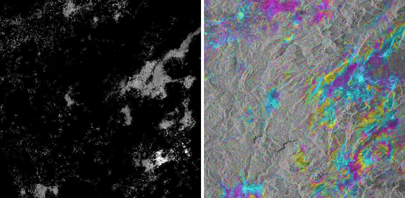
This area is well represented and the coherence is good, but the surrounding low coherence zones are can affect the SBAS inversion process and eventually the measurement accuracy. However, if there are enough interferograms (theoretically at least five per acquisition) the program is able to "reconstruct" the missing information by means of the 3-dimensions unwrapping approach.
Q. - What is the Unwrapping Approach adopted for the interferogram series?
A. - Actually the unwrapping execution depends on the Interferometric Stacking approach which is adopted:
❖ in the Persistent Scatterers, based on the original publication of Ferretti et al., the unwrapping is not performed for the estimation of the displacement rate and height corrections, since a pixel-wise spectral analysis approach in the time-baseline plane is exploited; this approach has the advantage of avoiding the need of unwrapping by working on the complex data only.
❖ in the SBAS Inversion, it is possible to choose between two main methods: Region Growing or Minimum Cost Flow, this last one either with a square or with an irregular triangulated - Delaunay - grid (Preferences>Interferometry). In case the Delaunay method is adopted, a 2- or 3-dimensions unwrapping (the third dimension being represented by the time) can be selected. At this regards it must be noted that the 3-dimensions approach provides superior results when there are disconnected areas (typically due to low coherence), as it exploits the high coherence interferograms (third dimension) to estimate how to create new connections in "scattered" (low coherence) interferograms; the disadvantage of this method is that it is much more costly in terms of processing time. The unwrapping, in the SBAS processing chain, is carried out two times: once before a first estimate of average displacement rate and height correction and once more afterwards to refine the first results.
Q. - Are there specific indications or rules to optimally set the Decomposition Levels?
A. - There are not specific rules since the optimal setting of this parameter depends strongly on the scene coherence and also on the unwrapping method adopted. In most of the cases, especially when the Delaunay method is adopted, the use of 1 decomposition is a good and robust setting. Sometimes good results are obtained by increasing the decomposition level from 1 (in the 1A - Interferometric Workflow step) to 2 (in the First Inversion step).
In any case, also relying on very precise orbits, the use of the "Orbital GCP file" is mandatory as the reflattening process must be always executed in order to correct the phase offset (i.e. constant phase removal).
Q. - What is the best way to analyse the SBAS results?
A. - The output products are grouped in meta files in order to make easier the simultaneous multi-temporal analysis. The meta files can be interpreted using either the raster data analyzer.