|
<< Click to Display Table of Contents >> Basic Module - Frequently Asked Questions |
  
|
|
<< Click to Display Table of Contents >> Basic Module - Frequently Asked Questions |
|
Q. - In the Data Import (Generic Binary or Generic Binary Geocoded), how can I know if the byte order of the input data is MSBF or LSBF?
A. - This information is generally provided in the data header file: MSBF corresponds to Motorola or Big Endian data type; LSBF corresponds to Intel or Little Endian data type. It must be noted that the byte order of an imported file can be transformed (from MSBF to LSBF and vice versa) using the relevant SARscape tool.
Q. - Can I run the Image Coregistration using any overlapping image, which is acquired by the same sensor?
A. - A mandatory requirement for image coregistration is that the "reference file" (Reference image) and the "input files" (images to be coregistered onto the Reference) are acquired with the same viewing geometry. It means that the data must have been acquired from the same satellite track and with the same incidence angle (i.e. same beam mode).
Q. - What to do if the automatic Image Coregistration process fails?
A. - Whether the coregistration process fails using the default Preferences, the number of windows (and if necessary also their size), in range and azimuth direction, should be increased. A manual location of the coregistration window can also be done.
Q. - I have been able to perform the Image Coregistration in SARscape with a completely automatic process. Is there a way to perform this process manually and when it can be eventually needed?
A. - The automatic coregistration process is successful in most of the cases and a sub pixel accuracy is achieved. However it can happen that large portions of the scene (typically homogeneous areas such as water, forest, sand, etc.) lack of spatial features, which are required for calculating the cross-correlation function between Input and Reference files. In these cases it is possible to manually locate points (Coregistration file), representing the center of the coregistration windows, in those areas where cross-correlation features (e.g. scatterers such as rocks, urban settlements and other man made objects) exist.
Q. - Is it possible to Coregister data acquired in different modes (e.g. Stripmap, Spotlight, ScanSAR) or by different satellites?
A. - It makes no sense to coregister data acquired with different geometries and the program will end with an error if the "reference file" and the "input files" are acquired from different satellite tracks or with different incidence angles. The way to have data, acquired with different geometries, comparable in terms of pixel location, it is to geocode them onto the same cartographic reference system.
Q. - Is it possible to Coregister SAR images acquired with the same viewing geometry but with different polarization? For instance an HH-HV acquisition with VV-VH acquisition?
A. - This can be done for instance by coregistering the co-polarization of the two acquisitions (HH - VV) and then apply the calculated "Shift Parameter file" for the coregistration of the cross-polarisations (HV - VH). It must be recalled that, if the "Shift Parameter file" is entered as input, the "Compute Shift Parameters" flag must be set off.
Q. - Which Damping Factor is used in the Frost Filter?
A. - The "dumping" factor is not specified in the SARscape implementation; this implementation actually foresees an "alpha" factor, which is automatically estimated by the program.
Q. - The result of the Anisotropic Non-Linear Diffusion Filtering shows regularly distributed horizontal striping/banding. What is the reason and how can it be avoided?
A. - The banding effect is due to border conditions on the speed-up Additive Operator Splitting scheme used for the Non-Linear diffusion steps. It is generally removed (or strongly reduced) be increasing the number of "Anisotropic Iterations" and possibly also the number of "Non-Linear Iterations".
Q. - What can I do to identify, in the Slant Range image geometry, a small area that I know in terms of Cartographic Co-ordinates?
A. - An automatic transformation, from cartographic to slant (or ground) range co-ordinates, can be carried out by means of the Geocoding>Map to Slant/Ground Point Conversion; likewise a geocoded image can be re-projected in slant (or ground) range geometry using the Geocoding>Map to Slant Range Image Transformation. These two approaches enable to locate a know geographic area (in form of map, image or points) in the SAR image viewing geometry. It must be noted that the accuracy of this transformation depends on the quality of the orbital parameters in the input SAR image.
Q. - The PC got stuck while Geocoding a COSMO-SkyMed stripmap product?
A. - The problem is possibly due to the "Block Size" dimension, which is set in the Geocoding Preferences. Using very high resolution data this parameter should be reduced in order to avoid memory allocation problems.
Q. - Geocoding ALOS PALSAR level 1.5 products, as well other ground range or geocoded original data, does not provide very accurate "geo-located" results?
A. - The range-doppler approach, which is normally applied in SARscape for the geocoding process, cannot be directly applied when ground range or geocoded products are inputted. In such case the map to slant transformation polynomial, which are included in the original product, are used to restore the original slant range geometry; if the conversion polynomial are not precise also the geocoding is not accurate. For this reason we strongly recommend to work with slant range (i.e. Single Look Complex) original data.
Q. - Can I convert a Geocoded Image into a SAR Slant Range Image viewing geometry?
A. - There is a specific functionality, in the Geocoding menu, to perform this process.
Q. - I've just acquired ALOS PALSAR FBD (level 1.1) data and I want to Geocode them. Are the orbits accurate enough to allow precise geocoding even without GCP or orbital correction?
A. - As far as our experience is with ALOS data, the orbits are precise enough to allow accurate geocoding of PALSAR products without any GCP and without applying any orbital correction; of course we recommend to use a DEM in input to the geocoding (and radiometric calibration) process in order to properly represent the geometry and radiometry of your output geocoded and calibrated product.
Q. - Why some ALOS PALSAR Level 1.0 Products (i.e. RAW data) are affected by Geolocation Inaccuracies?
A. - An error in the scene acquisition time, which is one of the parameters used for the image Geocoding, in some instances has been found in the data focussed with SARscape. The problem has been solved in the 4.1 release of the software. In case this problem was still reported, the use of a GCP in the geocoding process is required. Users reporting such problems are kindly asked to contact us and provide relevant data samples in order to optimize the software performance.
Q. - I want to improve the Geolocation Accuracy of Optical Data by means of Ground Control Points collected on SAR very high resolution images? What is the precision I can achieve using data such as COSMO-SkyMed or TerraSAR-X?
A. - The geolocation accuracy of both CSK and TSX data processed in nominal mode (i.e. geocoded without GCPs) is very good, in the order of the pixel. This means that you can use such products for your purposes.
Of course, in presence of relief, it is important to have a reference DEM in order to properly represent (and locate) the pixels on slopes. In the geocoding process, it would be ideal to use a DEM whose grid size is comparable with the SAR input data (i.e. better than 10 m resolution); however, in case this is not available, also the SRTM-3 can be fruitfully exploited.
Q. - What is the difference between Coregistered and Geocoded products?
A. - Both products (i.e. a coregistered temporal series or a geocoded temporal series) have the characteristic that each image of the series spatially match with the other images. The difference is that, coregistered data are referred to a relative system (i.e. the Reference acquisition geometry) and the pixel spacing is driven by the Reference file; geocoded data are referred to an absolute system (i.e. the cartographic reference system) and the pixel spacing depends on the real ground spatial resolution of each image of the series.
Q. - How does SARscape calculate the Incidence Angle when the DEM is not provided as input to the Geocoding process?
A. - In such case the program uses an ellipsoid whose reference height is entered, together with the other input cartographic parameters.
Whatever is the SAR input image (PALSAR, ASAR, etc.), the local incidence angle can be computed with or without an input DEM. In the first case its variation depends both on the pixel position in range direction (since the incidence angle varies from a minimum in near range to a maximum in far range) and on the local topography; in the second case the angle variation depends only on the pixel position in range direction (it resembles a ramp).
It is possible, by checking the Local Incidence Angle flag, to output the incidence angle map corresponding, pixel by pixel, to the geocoded image.
Of course the incidence angle depends on the SAR acquisition geometry (changing from the steepest to the least steep beam, the angle in the scene center varies from around 20° to around 50°). Moreover the angle variation, from near to far range, increases from Spotlight to Stripmap to ScanSAR acquisition modes.
Q. - I am working on assessing temporal signals with a SAR temporal series acquired with the same viewing geometry. If I adopt the Multitemporal De Grandi Filter, is there any risk to wash out the temporal signal?
A. - The De Grandi multitemporal filter has the peculiarity to preserve the temporal signature at the best and to dramatically reduce the speckle at the same time; this is especially evident when you have a set of 5, 6 or more coregistered images in input. However it can happen that, if you are using a temporal series where the differences among each acquisition are exceptionally strong in most of the imaged area extent, the temporal signal can be somewhere mixed.
Q. - Is it possible to Orthorectify images and what are the data/formats supported?
A. - All supported SAR sensors are suitable for orthorectification. The process is carried out once a Digital Elevation Model is entered in input to the Geocoding step. Slant as well as ground range products can be orthorectified; geocoded and georeferenced data (e.g. GEC products) cannot be, since they have already been corrected (i.e. projected) using a reference ellipsoid. In general the utilisation of ellipsoid geocoded products should be avoided, whilst slant range format (i.e. SLC) should always be adopted in order to achieve, using SARscape, an excellent geometric and radiometric data calibration based on an input Digital Elevation Model.
Q. - What is the advantage of using the Optimal Resolution approach with respect to the other interpolation methods?
A. - Using an interpolation method other than the "Optimal Resolution", the pixel values geocoded in a given map coordinate system are obtained (with respect to the interpolation part) using common resampling methods, which are approximations of a sinc-function. Whenever the "Optimal Resolution" approach is selected, the 4 range-azimuth positions corresponding to the 4 vertexes of the output pixel (typically the DEM) are determined and, subsequently, the average of the pixel values contained in the polygon is computed. This means that the size and shape of the slant-range polygon is locally adapted according to the local topography, which is not the case if the multilooking process is performed prior to the geocoding. Finally it is worth mentioning that the "Optimal Resolution" approach should be adopted only when single look data are geocoded to a significantly lower spatial resolution; in the other cases the "4th Cubic Convolution" resampling method is recommended.
Q. - Why the
area, in geocoded and radiometrically calibrated SAR amplitude images as well as in the layover map, is much bigger than the actual slope extent?
A. - The layover effect, which characterizes those slopes whose inclination is steeper than the radar look angle, extends far beyond than the slope itself. The zone affected by the layover corresponds to that area where the sensor-target distance decreases (i.e. the top of the slope is imaged before than its foot), while it should increase assuming a "flat earth". For this reason the beginning of the layover area is before the foot of the slope and its end is after the top of the slope (see figure below).
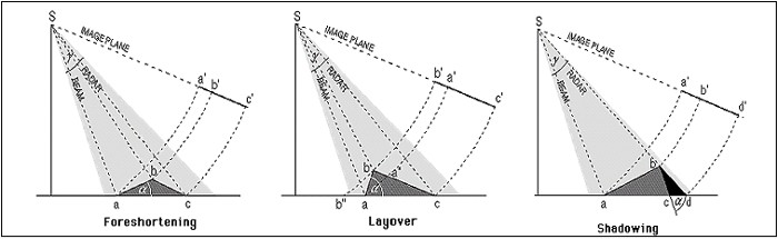
It must be noted that the quality - and reliability - of the geocoded products (i.e. SAR image and layover/shadow mask) depends on quality and resolution of the input DEM. The layover and shadow map can be generated starting from slant as well as ground range products; it cannot be done starting from geocoded data (e.g. GEC products).
Q. - Are the Layover and Foreshortening areas corrected as result of the Geocoding and Radiometric Calibration step?
A. - The foreshortening areas are corrected in terms of both radiometry and geometry. Vice versa the process can not resolve the ambiguities due to the representation of several points on the ground by one single point on the image (layover conditions); in these areas the information is missing and thus it cannot be recovered.
Q. - I see some strange artifacts in the Layover and Shadow Mask, which is generated in the Geocoding and Radiometric Calibration step; I also have the impression, by comparing the mask with the geocoded SAR image, that the extent of the masked areas does not exactly correspond to the layover/shadow zones. What is the reason of the mask artifacts and discrepancies?
A. - The quality of the layover shadow mask depends only on the input reference DEM. One cannot expect a better mask by using a SAR image with a better resolution, if the input DEM remains the same and, in case of artifacts in the DEM, they will come up also in the layover shadow mask. The SAR input data are considered only for what concerns the acquisition geometry and in particular for the calculation of the Local Incidence Angle.
Concerning the extent of the masked areas, what typically happens it is that, if you visually compare the very bright and very dark areas in your SAR image with respectively red and blue pixels in the mask, you perceive an underestimation of the masked areas, but if you go to check the local incidence angle values (_lia output product) you discover that these are the only pixels actually affected by layover or shadow.
Q. - Why is the Calibrated Value dimensionless?
A. - The calibrated value is a backscatter coefficient, which corresponds to the ratio between the transmitted and the reflected power; this explains why it is a dimensionless number. SARscape normally generates the calibrated data in linear scale (for a distributed target you would expect a value between 0 and 1), but you have also the optional flag to additionally generate outputs in dB.
Q. - I have a Radarsat-2 Wide Swath full polarimetric acquisition in SLC format. I want to know how to get a Calibrated Product in dB units.
A. - The calibration process - independently from the satellite, acquisition mode and polarization and also independently from the original data format - is performed during the geocoding and radiometric calibration step. The default calibrated value is a normalized dimensionless number (linear units); the corresponding value in dB (10*log10 of the linear value) can be additionally generated by checking the relevant flag in the processing panel. The calibrated output is normally generated as georeferenced products, but you can also choose to have it in the original satellite viewing geometry (slant range, not geocoded image) by checking the relevant flag in the panel. The default calibrated value is Sigma Nought, nonetheless the Gamma Nought and
Beta Nought can be (additionally or alternatively) generated by setting the appropriate flag in the Preferences>Geocoding (Backscatter Value section).
Q. - What are the parameters which are taken into account when the Data Calibration is carried out?
A. - The data calibration parameters are provided, for some sensors (e.g. Radarsat-1), in the standard product header file; in other cases the calibration parameters are annotated within ancillary files (e.g. XCA file for ENVISAT ASAR data), which must be inputted during the Data Import step in order to be used later on during the "Geocoding and Radiometric Calibration" step. SARscape can calibrate any supported SAR product (both in slant range and ground range geometry), following the radar equation principle.
The radiometric calibration, which is carried out in SARscape for distributed targets, involves corrections for:
1.the scattering area - each output pixel is normalized for the actual illuminated area of each resolution cell, which may be different due to varying topography.
2.the antenna gain pattern - the effects of the variation of the antenna gain in range are corrected, taking into account the real topography (DEM) or a reference height.
3.the range spread loss - the received power must be corrected for the distance changes in range direction.
It must be noted that, in case the objective is to precisely estimate the data calibration parameters (both for point targets and distributed targets) and/or to assess the product quality in terms of radiometry and geometry, then a specific tool should be adopted. Such "Quality Assessment Tool" has been recently developed as SARscape additional module.
Q. - I would expect to obtain a Radiometrically Calibrated Product where the pixel values are either positive or negative, while I only obtain positive values whose majority is between 0 and 1.
A. - It is correct that, if you are analysing a calibrate image in dB, the values shall be either positive or negative. Vice versa, if you are analysing a calibrated image in linear units (this is the standard/default setting in SARscape), the backscatter of distributed targets usually varies from 0 to 1 (you can have values higher than 1 in case of very bright scatterers or point targets, but you'll never get negative values). In order to generate the output in dB, you have to flag the "Additional Output dB" flag in the geocoding panel and you have to analyse the output products which is marked by the extension "_dB".
Q. - Why the Radiometric Calibration is performed in the data geocoding step, particularly when the calibration parameters are included in the metadata?
A. - The radiometric calibration of SAR data depends both on some sensor-related calibration factors contained in the metadata and on geometric factors that depend on the local topography of each pixel (e.g. pixel scattering area, incidence angle related with the true local height). Therefore, while the first group of calibration factors can be applied in any step, for the second case the knowledge of the real topography that corresponds to each imaged pixel is necessary to be able to carry out the calibration (without just considering a constant reference height, therefore introducing severe approximations and errors in the calibration of non-flat areas), and this information is available at best during the geocoding step (when the relationship between each pixel in SAR coordinates and the corresponding location in a cartographic reference system over a DEM is computed). In particular concerning the calibration factors contained in the metadata, they are ingested (and written in the .sml header file) during the data import, to be properly accounted for afterwards during the "Geocoding and Radiometric Calibration" step.
Q. - Concerning the Antenna Gain pattern and the Range Spread Loss, are the Single Look Complex Standard Products already provided (original products from official distributors) as Calibrated , or this correction is performed inside the SARscape processing chain?
A. - The adopted procedure usually depends on the different sensors; in few cases, also for the same sensor, there are some standard/original products which are provided already corrected, while some others are not. As an example in case of the PALSAR 1.1 product the data come already corrected in terms of antenna gain and range spread loss (this happens also for other SLC data such as most of the COSMO-SkyMed standard products, even if there are some exceptions for what concerns the ScanSAR SLC data...). In other cases, such as ASAR or ERS, the correction is done during the geocoding process. A different way is followed when RADARSAT data are processed: here the correction is performed during the import step.
Q. - What is the best way (Local Incidence Angle or True Area) to compute the Scattering Area for the Radiometric Calibration?
A. - The "True Area" method is doubtless more rigorous, but it is also more time consuming and the output product quality strongly depends on the accuracy of the input Digital Elevation Model. The "Local Incidence Angle" method is more simplistic, but much faster in terms of processing time; as a matter of fact, in case of a coarse input DEM (with respect to the SAR data pixel sampling), the results provided by the two methods are very similar and thus in such case the "Local Incidence Angle" is often preferred.
Q. - I'm using the True Area method for the Calibration of a Radarsat-2 image, using a 10 meters resolution Digital Elevation Module. I see that some topographic effects are still visible, mainly on top of hillsides facing towards the satellite, which get very bright. Can these effects be corrected?
A. - The True Area approach implements an oversampling of the input DEM, which is aimed at precisely estimating the scattering area. The strong brightness on the slopes facing the sensor can be eventually better corrected by increasing the oversampling factor to 6 or more.
Q. - What does the Sigma Nought value represent?
A. - The sigma nought is the scattering coefficient, the conventional measure of the strength of radar signals reflected by a DISTRIBUTED (not point) scatterer. In SARscape it is typically presented in linear units; the corresponding value in dB can be calculated as: 10*log10 (calibrated pixel linear value).
Q. - How can be the linear (decimal figure) Calibrated value transformed into dB value?
A. - The db value can be calculated by applying 10*log10 to the corresponding decimal unit (linear varying measure).
Q. - How can be the Calibrated dB value converted in linear (decimal figure) units?
A. - The conversion is obtained by applying 10dB/10; where the "dB" exponent is the backscatter value measured in dB.
Q. - Why Calibrated data contain values higher than 1?
A. - The SARscape calibration is conceived to work on distributed targets; for this reason the calibrated value of local scatterers is not reliable. Local strong scatterers can have values higher than 1.
Q. - Why the ENVISAT ASAR Calibration parameters are often updated and new XCA Files are consequently released by ESA? How SARscape takes into account for the updated calibration parameters?
A. - The release of updated XCA files is based on the results of ESA calibration campaigns, where possible variations in the instrument performance are taken into account by tuning the relevant parameters. As a matter of fact what usually changes is the antenna gain pattern (AGP), rather than the calibration constant (K). This is often due to deterioration or damages affecting the antenna hardware itself, which in most of the cases affects the antenna gain in a different way depending on the acquisition mode.
SARscape uses the XCA parameters, which are stored in the "description files" directory within the program installation folder (these are updated with the latest XCA released by ESA until the date of the SARscape release). If the required XCA file is not available within the installation package, a warning message will appear advising to download this file from the relevant ESA web site. It is suggested to store this new XCA file within the "description files" directory in order to make it available for further ASAR data.
Q. - Where are the Look Up Tables, which come with the original Radarsat-1 product, used for the Data Calibration?
A. - The Look Up Tables (lutBeta.xml) are ingested and accounted for when the original product is imported.
Q. - What are the data formats mostly suitable for Data Calibration purposes?
A. - Original Single Look Complex data are suggested to derive absolutely radiometric calibrated values. Level 0 product (i.e. RAW data) have not to be used if the objective is to get a meaningful calibrated image, since some crucial parameters such as the antenna gain are not properly taken into account when the data are focussed with SARscape. It is possible to experience any anomalous and unexpected behaviour of the intensity data when level 0 products are focussed with SARscape and afterwards calibrated and normalised.
Q. - How to choose the optimal Radiometric Normalization method and factor? Are there specific values to set depending on the acquisition sensor?
A. - The difference between the "Semi-empirical correction" method and the "Cosine correction" method is that the first one implements an automatic procedure (linear regression between the cosine of the local incidence angle and the backscattering coefficient in logarithmic form) to estimate and compensate the dependency of the backscatter from the cosine of the local incidence angle referred to the topography; the second method uses an empirical correction factor (Normalisation Degree) to compensate the backscattering coefficient for range variations only (the topography is not taken into account); there is not a fixed value for the correction factor, it must be tuned proportionally to the incidence angle variation from near to far range: the larger is the incidence angle difference between near and far range the bigger the normalization degree must be. Being the normalization degree an empirical parameter, the optimal setting can be found by checking the similarity between the values of same land cover type in the near and in the far range of the output calibrated (and normalised) image.
Q. - Why the pixel value does not change between Radiometrically Calibrated and Radiometrically Calibrated + Normalized product?
A. - The Normalisation is intended to empirically correct the dependency of the backscattered signal from the incidence angle, which varies with the topography and with the position in range direction. This implies that the calibrated values does not change dramatically with respect to calibrated + normalised values; in particular the change between the two values is expected higher in the near/far range positions and smaller in the mid range position.
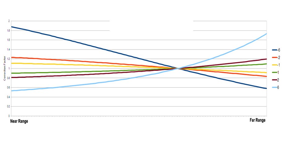
Q. - I'm doing the Normalization (cosine correction method) of an ASAR WS level 0 image that I've previously Focussed with SARscape, I achieved the best results by using the value -2, which I guess should not be valid. Can you explain why?
A. - As reported in the relevant section of the online help, the data calibration (and normalization as well) is not reliable when the processing is performed on original RAW data, which are focussed with SARscape. This is essentially due to the fact that the implemented focusing algorithm does not have the possibility to update important parameters such as antenna gain, calibration constant and others. The cosine correction method is intended to apply an empirical correction factor; positive factors allow increasing the original value from the near to the far range of the image, normalizing in this way a "ramp" that is normally going from higher vales in near range to lower values in far range (this ramp being due to the different scattering mechanism of the same targets, when observed with different viewing angles). It can happen that this ramp has an "unexpected" inclination when some calibration related parameters, such as the antenna gain or others, are incorrect; this can be the case when the processing is performed starting from original RAW data. In particular, in your example, the ramp was actually inverted with respect to the normal trend; that's why the negative factor worked well. The graph below shows how the correction varies, from the near to the far range, depending on the different factor which is entered for the normalization. The graph reports the curves relevant to factors ±6, ±2 and ±1.