|
<< Click to Display Table of Contents >> Interferometry - Interferometric Tools -Displacement Decomposition |
  
|
Interferometry - Interferometric Tools -Displacement Decomposition
|
<< Click to Display Table of Contents >> Interferometry - Interferometric Tools -Displacement Decomposition |
|
Purpose
Displacement Decomposition tool calculates the vertical, east-west and optionally north-south components of the displacement. For 2D decomposition more than one DInSAR displacements measurements are needed over the same area of interest. For 3D decomposition (2D+1D, 1D+2D) more than two DInSAR displacements measurements are needed over the same area of interest.
Technical Note
This tool exploits displacement measurements obtained from different acquisition geometries to retrieve the displacement components along east-west, vertical and optionally north-south. This tool can deal with geocoded DInSAR displacement only (in raster format).
Results from different sensor are supported.
Minimum input data requirements for 2D decomposition options are:
- 1 Ascending and 1 Descending geometry measurements ;
- 2 Ascending or 2 Descending (with at least a difference of 10° incidence angle between the Line of Sight of the input geometries, as for example, near-range and far-range over the same area of interest).
Minimum input data requirements for 3D (2D+1D Theoretical: north component is derived from theoretical assumptions, its accuracy is lower than the east-west and vertical component) decomposition options are:
- 1 Ascending and 2 Descending geometry measurements;
- 2 Ascending and 1 Descending geometry measurements;
- >1 Ascending and >1 Descending (with at least a difference of 10° incidence angle among the Line of Sight of the input geometries, as for example, near-range, medium-range and far-range over the same area of interest), best option.
Minimum input data requirements for 3D (1D+2D) decomposition options are (north component accuracy is lower than the east-west and vertical component):
- 1 Multi-Aperture Interferometry/Amplitude tracking along satellite flight direction measurement, 1 Ascending and 1 Descending geometry measurements;
- 1 Multi-Aperture Interferometry/Amplitude tracking along satellite flight direction measurements, 2 Ascending or 2 Descending geometry measurements (with at least a difference of 10° incidence angle between the Line of Sight of the input geometries, as for example, near-range, medium-range and far-range over the same area of interest).
In order to obtain a more reliable decomposition result, a higher number of input are suggested, since the decomposition kernel applies a weighted least-square inversion. The weights are derived from the LOS displacement precision.
Please note: _ALOS, _ILOS, _precision, _dem ancillary files have to be in the same folder specified for the requested input _disp file (measured displacement generated by the DInSAR, MAI, Amplitude tracking processing).
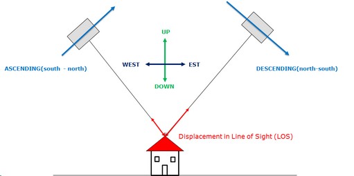
Sign convention:
vertical direction: positive values upward, negative values downward;
east-west direction: positive values eastward, negative values westward;
north-south direction: positive value northward, negative value southward.
Please note: the north-south component accuracy is limited due to the geometrical acquisition of SAR data, with respect to east-west and vertical direction
Basic input DInSAR measurement configuration for 2D decomposition (figure 1 below).
Optional higher redundancy input DInSAR measurement configuration for 2D and 3D decomposition (figure 2 below).
Each displacement measure is fully described by the magnitude and the angles (azimuth and inclination) of the satellite Line Of Sight.
Input Files
File name of the displacement file (_disp, _velocity_geo). This file is mandatory (please, refer to technical notes).
Principal Parameters
Displacements Decomposition Type
The options for DInSAR displacement decomposition are:
•Decomposition 2D, decomposition in vertical and east-west directions.
•Decomposition 2D+1D (Theoretical), decomposition in vertical and east-west directions (2D), and north-south direction (1D).
•Decomposition 1D+2D, decomposition in vertical (1D), and east-west and north-south directions (2D); in case of availability of Multi-Aperture Interferometry/Amplitude tracking along satellite flight direction measurement.
Output Files
Output Root Name
Name of the output root. This file is mandatory.
_decomposed_east_disp
Displacement component along the East-West direction.
_decomposed_vertical_disp
Displacement component along the vertical direction.
_decomposed_north_disp
Displacement component along the north-south direction.
_decomposed_east_Dprecision
Displacement precision component along the East-West direction.
_decomposed_vertical_Dprecision
Displacement precision component along the vertical direction.
_decomposed_north_Dprecision
Displacement precision component along the north-south direction.
_DEM
Weighted average DEM combination.
_inXXALOS
Input ALOS file.
_inXXILOS
Input ILOS file.
Details specific to the Units of Measure and Nomenclature of the output products can be found in the Data Format section.
General Functions
Exec
The processing step is executed.
Store Batch
The processing step is stored in the batch list. The Batch Browser button allows to load the batch processing list.
Close
The window will be closed.
Help
Specific help document section.
Specific Function(s)
None.
Task, SARscapeBatch object, SARscapeBatch script example
References Fialko Y., Simons M., 2001. The complete (3-D) surface displacement in the epicentral area of the 1999 Mw 7.1 Hector Mine earthquake, California, from space geodetic observations. Geophysical Research Letters, vol. 28, no 16, pp 3063-3066. Ng, Alex Hay-Man, et al. "Deformation mapping in three dimensions for underground mining using InSAR–Southern highland coalfield in New South Wales, Australia." International Journal of Remote Sensing 32.22 (2011): 7227-7256.