ENVI Modeler Example: Using Conditional Operators with Rasters
This topic provides different examples of using the ENVI Modeler to apply conditional operators to one or more bands in a raster. Use the Band Math node to do this. The Band Math node is a pixelwise operation, meaning that it applies mathematical and conditional expressions on a pixel-by-pixel basis.
This example is designed to show concepts without using any specific datasets. You must supply your own datasets to follow the steps here.
See the following sections:
- Operations on a Single Band
- Operations on Bands from Different Rasters
- Change Pixel Values
- Related Tasks
Operations on a Single Band
You can use logical operators such as AND, OR, and NOT to test a condition. Logical operators are often used in combination with relational operators such as GT (greater than), LT (less than), EQ (equal to), GE (greater than or equal to), and LE (less than or equal to). If the conditions are met in a given pixel, that pixel's value is set to 1 (true). All other pixel values are set to 0. The result is a binary raster.
An example is identifying pixels within a certain range in a digital elevation model (DEM). The following scenario uses a U.S. Geological Survey Shuttle Radar Topography Mission (SRTM) DEM for illustration.
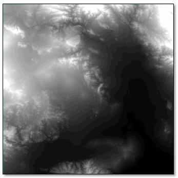
Suppose that you want to identify pixels that range in elevation from 1500 to 3000 meters. Follow these steps:
- Connect the Band Math node to a File (or other input) node.
- Click the
 button in the Band Math node. Enter the condition in the Expression field of the Band Math dialog, then click OK. For example:
 - Connect a View node to the end of the model.
- Run the model. A binary image appears in the display as completely black.
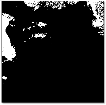
- Apply an Equalization stretch using the Stretch Type drop-down menu in the toolbar. Now the image appears in black (value=0) and white (value=1). Pixels with a value of 1 meet the condition specified in the Expression field.
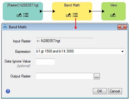
Name the variables (bands) using a convention of bx, where x is the order of the band in the raster. In this example, the DEM is a single-band raster, so the variable is b1.
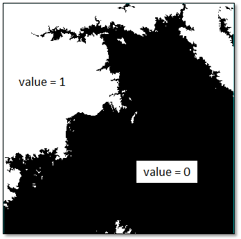
You can use binary rasters as masks. Or you can create color slices of the binary values, convert them to classes, and convert the classes to shapefiles using the Raster Color Slice tool.
Operations on Bands from Different Rasters
You can also apply a conditional statement to two or more bands from different rasters. In this case, add a Build Band Stack node before the Band Math node if the bands are already coregistered. Or add a Build Layer Stack node if the bands are not coregistered or georeferenced. The Build Layer Stack node lets you resample one or more rasters to the same spatial grid as one a designated raster, so that they line up correctly.
The following example uses a Topographic Modeling node to calculate slope (in degrees) from a DEM. Because the DEM is already georeferenced, and the Slope image was derived from it, the Build Band Stack node is used to stack the two images into one raster. Then you can apply a conditional expression that locates pixels where the elevation is greater than 2000 meters and the slope is less than 30 degrees.

Follow these steps:
- Connect a Topographic Modeling node to a File (or other input) node.
- Click the
 button in the Topographic Modeling node.
 - Select Slope from the Products list, then click OK.
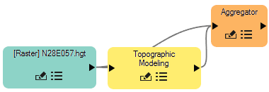
- The Build Band Stack node accepts an array of input rasters, so you must add an Aggregator node first. This will collect the input rasters (the DEM and the Slope image) into an array. Connect the File node and the Topographic node to the Aggregator node:
- Connect a Build Band Stack node to the Aggregator node.
- Connect a Band Math node to the Build Band Stack node.
- Click the
 button in the Band Math node.
 - Enter a conditional expression; for example, b1 gt 2000 AND b2 lt 30.0. The term b1 is the DEM band, and b2 is the Slope image.
- Connect a View node to the end of the model.
- Run the model. A binary image appears in the display as completely black.
- Apply an Equalization stretch using the Stretch Type drop-down menu in the toolbar. Now the image appears in black (value=0) and white (value=1). Pixels with a value of 1 meet the condition specified in the Expression field.

Change Pixel Values
You can also use the Band Math node to change pixel values. A common scenario is to reassign class values in a classification image. This can be useful when you are working with multiple classification images where the same class type (such as forest) is classified as a different class value in a different classification image. The key is to use the correct syntax to get the expected results.
Here is an example expression that changes all class pixel values of 1 to a value of 2:
2 * (b1 eq 1) + b1 * (b1 ne 1)
The first part of the equation, 2 * (b1 eq 1), creates a mask where pixel values equal to 1 are set to 1 and all other values are set to 0. Multiplying this result by 2 sets the "1" pixels to 2. The second part of the equation, b1 * (b1 ne 1), creates a mask of 1 values wherever the pixels do not equal 1, and the pixels that do equal 1 are set to 0. Multiplying this mask by the original image sets all values of 1 equal to 0 while retaining the original image values everywhere else. Adding these two images gives the desired result: pixel values of 1 are now set to 2, while other pixels remain the same.
Related Tasks
Instead of using the Band Math node, consider these other Task nodes:
- Binary Greater than Threshold Raster: Create a new raster where values above a threshold are set to 1 and all other values are set to 0.
- Binary Less than Threshold Raster: Create a new raster where values less than a threshold are set to 1 and all other values are set to 0.
- High Clip: Create a new raster where values above a threshold are set to the threshold.
- Low Clip: Create a new raster where values below a threshold are set to the threshold.
See Also
Band Math, IDL Tips for Use in Band Math, Band Math User Functions