|
<< Click to Display Table of Contents >> Preferences specific - SBAS |
  
|
|
<< Click to Display Table of Contents >> Preferences specific - SBAS |
|
This panel enables to set the default processing parameters which are used in those functions related to the SBAS processing.
Technical Note
None.
Input Parameter(s)
Connection Graph Min Normal Baseline (%)
This threshold corresponds to the minimum percentage of the critical baseline value, which is considered acceptable in the generation of the possible data connections.
Connection Graph Max Normal Baseline (%)
This threshold corresponds to the maximum percentage of the critical baseline value, which is considered acceptable in the generation of the possible data connections.
Connection Graph Min Temporal Baseline (days)
This threshold corresponds to the minimum temporal distance, which is considered acceptable in the generation of the possible data connections. This value is expressed in days.
Connection Graph Max Temporal Baseline (days)
This threshold corresponds to the maximum temporal distance, which is considered acceptable in the generation of the possible data connections. This value is expressed in days.
Connection Graph Degree of Redundancy
After applying the thresholds on minimum and maximum Temporal and Normal Baseline for the connections (interferograms) selection, a further degree of redundancy selection criteria can be specified:
•high, all the interferograms respecting the previous Baseline thresholds are accepted.
•low, the program tries to minimize the number of kept interferograms, based on the Graph Redundancy Criteria and on Min Connection per Acquisition
Connection Graph Redundancy Criteria
The following selection criteria are foreseen for the removal of redundant connections, when the Degree of Redundancy is low:
•Min Normal Baseline, the number of connections is minimized by keeping only those having the smallest spatial baseline.
•Max Normal Baseline, the number of connections is minimized by keeping only those having the largest spatial baseline.
•Min Temporal Baseline, the number of connections is minimized by keeping only those having the smallest temporal baseline.
Connection Graph Min connections per Acquisition
Number of connections (interferograms) per acquisition remaining after skimming to reduce redundancy. This parameter indicates the average redundancy of the connection graph, and bibliography suggest setting a value higher than 5 to obtain reliable inversion solutions.
Connection Graph Only Forward Pair
Selecting this option, those pairs where the Reference is acquired before the Secondary are inverted (i.e. the original Secondary image becomes a new Reference).
Connection Graph Allow Disconnected Blocks
By setting this flag the program does not discard any group of images (refer to the Technical Note) and the disconnected SBAS functionality is automatically activated for the next inversion steps.
The choices are the following:
oFalse: when the graph is not fully connected the disjointed acquisition blocks are rejected.
oAllow: the disjointed acquisition blocks are kept.
Connection Graph Delaunay 3D
By setting this flag a triangular connection network in the time baseline domain is generated, which is suitable for the 3-dimensional unwrapping (Refer to the Technical Note). This functionality is under maintenance.
Connection Graph Write Super Reference Power
Create and write the Super Reference power image.
Connection Graph Central Super Reference
Automatically selects the super Reference at the center of the time series. Especially useful for incremental processing with sliding windows.
Rebuild All
This flag refers to all SBAS process. By setting the flag the whole process is performed from scratch (if not incremental mode is active).
It is advisable to leave this flag unchecked in case of process interruption, so that the products already generated have not to be computed and stored again.
Number of Parallel Unwrapping
Defines the number of unwraps that will be performed in parallel (one interferogram for each thread). This parameter must not exceed the total number of CPU threads. The user should consider the available system memory before increasing the number of parallel processes, as the memory consumption is directly related to the number of unwraps performed in parallel.
Apply Layover and Shadow Mask
Mask the results in layover and shadow areas.
Classification Mask ID List
IDs used as a mask by the “Classification Mask File” in the SBAS interferometric Process. A list of IDs interspersed with a space, tab, comma, etc. can be entered.
Elevation Mask Threshold
Elevation threshold used for the elevation mask generation (mostly used to remove the temporal snow coverage). Elevations above the threshold, during the period specified by start and end month, will be masked.
Elevation Mask Start Month
Beginning of the validity period (in months between 1 and 12) of the elevation mask.
Elevation Mask End Month
Ending of the validity period (in months between 1 and 12) of the elevation mask. The end month is considered as included for the mask generation.
Keep Coregistration Ancillary Info
Store the coregistation windows parameters in .xls files in the SBAS working folder.
Inversion SVD Type
This flag refers to both inversion process. Two options are available for this inversion:
•SVD jacobi, which is slow but more stable with respect to
•SVD bdc, which is 4-5 times faster but less stable (the process can exit directly without triggering any error code) in case of ill posed matrix to invert. This could happen when allow disconnected blocks is selected and few valid phase measurements, with respect to variable number, are available.
In any case both the techniques will provide the same result accuracy.
Inversion Weighted Solution
This flag refers to both inversion process. The equations and measured phase in the SBAS inversion are weighted with their theoretical precision. The theoretical precision is related to the coherence values, through the conversion from coherence into phase standard deviation:
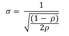
Where ρ is the spatial coherence.
Inversion Reject Outliers - Height (m)
This parameter refers to both inversion process. The equations, which residual height exceed this value, are rejected from the SBAS inversion. The residual height corresponds to the difference between the measured phase converted into topography height and the previous height grid point solution. If this value is smaller than 0 is not considered.
Inversion Reject Outliers - Displacement (mm)
This parameter refers to both inversion process. The equations, which residual displacement exceed this value, are rejected from the SBAS inversion. The residual displacement corresponds to the difference between the measured phase converted into displacement and the previous displacement grid point solution. If this value is smaller than 0 is not considered.
Inversion Step1 Displacement Model Type
The choice is given between the following models:
•no displacement, a stable area is considered, no displacement is calculated (this parameter set to true exploit the SBAS capability to calculate precise DEMs)
•Linear, the displacement velocity [mm/year] is calculated
•Quadratic, the displacement acceleration [mm/year2], and velocity [mm/year] are calculated
•Cubic, the displacement acceleration variation [mm/year3], the displacement acceleration [mm/year2] and velocity [mm/year) are calculated
•Linear Periodic, the periodic delay [days], the periodic modulation [mm] and velocity [mm/year] are calculated
Refer to the Technical Note for further information.
Inversion Step1 Model Period
Linear Periodic model expected period (days) in the processed scene. This parameter is considered only when the Displacement Model Type selected is Linear Periodic.
Inversion Step1 Estimate Residual Height
If selected, it estimates the residual topography height. This parameter should set to false on two situations:
1-In case of good quality high reference resolution DEM, topography component estimation is not necessary.
2-In case of less than 20 images, this could lead to a pour residual height estimation, and consequently a wrong velocity estimation, due to strong atmospheric artefacts (suitable for stack with small normal baseline as Sentinel). The most simply model selection (with just one free term) increases the result reliability.
When this parameter is selected, and the Displacement Model Type selected is no displacement, the SBAS is used for the generation of precise DEMs.
Inversion Step1 Spatial Wavelet Size (m)
It preserves the estimated residual topography data resolution till the specified value. It removes the low pass distortion under this resolution value and preserves the spatial details by using wavelet decomposition. If this value is smaller or equal to 0 is not considered.
Inversion Step1 Allow Disconnected Time Series
This option allows avoiding to discard separate group of acquisitions: the voids in the retrieved displacement temporal series will be interpolated by using the model chosen in the Displacement Model Type field (e.g. linear, quadratic or cubic). Anyway, the recommended setting to obtain more reliable results is to disable the Allow Disconnected Time Series option. Usually it may helps is increasing the coverage over low coherence areas.
The choices are the following:
oFalse: when the time series is not fully connected it is rejected.
oAllow: the results are provided even if the time series is not fully connected.
Inversion Step1 Min Valid Interferograms (%)
Percentage of the minimum number of accepted SBAS inversion equations (interferograms over the coherence threshold) for getting an acceptable result for each output grid point. This parameter is considered if it is equal or greater than zero valid interferogram and should be used when the Allow Disconnected Blocks is flagged (or the Allow disconnected Blocks has been previously flagged in the connection graph generation step).
Inversion Step2 Displacement Model Type
The choice is given among the following models:
•The same as first, use the same model used in first inversion,
•no displacement, a stable area is considered, no displacement is calculated (this parameter set to true exploit the SBAS capability to calculate precise DEMs)
•Linear, the displacement velocity [mm/year] is calculated
•Quadratic, the displacement acceleration [mm/year2], and velocity [mm/year] are calculated
•Cubic, the displacement acceleration variation [mm/year3], the displacement acceleration [mm/year2] and velocity [mm/year] are calculated
•Linear Periodic, the periodic delay [days], the periodic modulation [mm] and velocity [mm/year] are calculated
Refer to the Technical Note for further information.
Inversion Step2 Model Period
Linear Periodic model expected period (days) in the processed scene. This parameter is considered only when the Displacement Model Type selected is Linear Periodic.
Inversion Step2 Estimate Residual Height
If selected, it estimates the residual topography height. This parameter is considered only when the Displacement Model Type selected is no displacement (SBAS used for precise DEMs calculation only). The same as first option, use the same flag value used in first inversion.
Inversion Step2 Interpol Disconnected Time Series
By setting this flag the program provides the solution for disconnected coherent targets over the grid point. The temporal gaps, where the displacement measurement does not exist or have been rejected, are interpolated using the average trend estimated during the first inversion, or they are set to zero. The disconnected SBAS provides a higher solution spatial coverage, limited by the Min Valid Interferogram and Min Valid Acquisition percentage thresholds. The choices are the following:
oFalse: the temporal series with gaps are rejected.
oInterpol using model: the gaps are interpoled using the average trend estimated during the first inversion.
oInterpol starting from zero: the gaps are filled with zero. The temporal series start from zero at the end of this gaps.
Inversion Step2 Atmosphere Low Pass Size (m)
Enter the window size, in meters, to apply the spatial distribution related filter (refer to the Technical Note).
Inversion Step2 Atmosphere High Pass Size (days)
Enter the window size, in days, to apply the temporal distribution related filter (refer to the Technical Note).
Inversion Step2 Min Valid Interferograms (%)
Percentage of the minimum number of valid inversion equations (interferograms over the coherence threshold) for getting an acceptable result, at each output grid point. This parameter is considered if it is equal or greater than zero valid interferogram and should be used when the Interpol Disconnected Blocks is flagged (or the Allow Disconnected Blocks has been previously flagged in the connection graph generation step).
Inversion Step2 Min Valid Acquisitions (%)
Percentage for the minimum number of valid acquisitions (covered by at least a certain amount of valid interferogram over the coherence threshold) for getting an acceptable result, at each output grid point. This parameter is considered if is equal or greater than zero and should be used when the Interpol Disconnected Blocks is flagged (or the Allow Disconnected Blocks has been previously flagged in the connection graph generation step).
Inversion Step2 Min Valid Interf per Acquisition (reject)
Minimum number of interferograms to consider the acquisition date valid for the inversion. The rejected acquisition dates are interpolated using the average trend estimated during the first inversion, if the Interpol Disconnected Blocks flag is active.
Inversion Step2 Min Valid Interf per Acquisition (redundancy)
Minimum number of interferograms to consider reliable the estimated displacement for an acquisition date. If the number of interferogram is lower than this threshold, the process increases the redundancy using the average trend estimated during the first inversion. The effect of this additional average trend is to reduce the noise of the resulting time series when few interferograms/measures are available.
Geocoding Height Precision Threshold
Upper threshold of the height measurement average precision values (refer to the Phase to Height conversion for more details). This must be provided in meters. This threshold is used together with the Velocity Precision Threshold and the Product Temporal Coherence Threshold for the masking process.
Geocoding Velocity Precision Threshold
Upper threshold of the velocity measurement average precision values (refer to the Phase to Displacement conversion for more details). This must be provided in millimeter/year. This threshold is used together with the Height Precision Threshold and the Product Temporal Coherence Threshold for the masking process.
Geocoding Product Temporal Coherence Threshold
Lower threshold of the temporal coherence measurement values. This threshold is used together with the Height Precision Threshold and the Velocity Precision Threshold for the masking process.
Geocoding Water Mask (dB)
Vale in dB used as threshold to retrieve a water body mask from the average intensity image. All the points under this threshold will be removed from the output layers. Active if smaller than 0.
Geocoding Rebuild All
By setting this flag the whole geocoding process is started from scratch.
It is advisable to leave this flag unchecked in case of process interruption, so that the products already generated have not to be computed and stored again.
Geocoding Make Geocoded Raster
By setting this flag the output raster file/s are generated.
Geocoding Make Geocoded Shape
By setting this flag the output shape file/s are generated.
Geocoding Generate Shape Time Series
By setting this flag the output shape file/s, with the displacement temporal evolution, are generated.
Geocoding Generate Shape Counter Series
By setting this flag the output shape file/s, with the valid interferogram counter for each acquisition date, are generated. When the counter is zero, the correspondent acquisition date has been temporally interpolated. Higher the counter higher is the reliability of the corresponding estimated displacement measure.
Geocoding Set Temporal Interpolation Code in Time Series
By setting this flag the output shape and the raster displacement time series files contain a special floating-point coded value for the acquisition date temporally interpolated. This coding is used by the visualization time series analyzers, to highlight which points and which dates have been temporally interpolated.
Geocoding Set Spatial Interpolation Code in Time Series
By setting this flag the output raster displacement time series files contain a special floating-point coded value for the acquisition date spatially interpolated. This coding is used by the visualization time series analyzers, to highlight which points and which dates have been spatially interpolated.
Edit Reject Automatic Strong Discontinuities (%)
By setting a reject threshold higher than zero and clicking the Automatic button of the SBAS Edit Connection Graph panel, the worst interferograms (a percentage of the whole interferogram stack) are discarded from the stack. The reject and keep stack meta/series are generated as visual description of the automatic editing tool behavior. The corresponding last processed unwrapped meta/series is updated as well. The metric for the unwrapping interferogram sorting is the number of wrong discontinuity phaseflatt cycles with respect to the number of valid pixels.
Edit Reject Automatic High Std (%)
By setting a reject threshold higher than zero and clicking the Automatic button of the SBAS Edit Connection Graph panel, the worst interferograms (a percentage of the whole interferogram stack) are discarded from the stack. The reject and keep stack meta/series are generated as visual description of the automatic editing tool behavior. The corresponding last processed unwrapped meta/series is updated as well. The metric for the unwrapping interferogram sorting is the standard deviation.
Edit Reject Automatic Poor Coverage (%)
By setting a reject threshold higher than zero and clicking the Automatic button of the SBAS Edit Connection Graph panel, the worst interferograms (a percentage of the whole interferogram stack) are discarded from the stack. The reject and keep stack meta/series are generated as visual description of the automatic editing tool behavior. The corresponding last processed unwrapped meta/series is updated as well. The metric for the unwrapping interferogram sorting is the valid pixels coverage.
General Functions
Load Preferences
It allows loading specific Preferences tthirteen different settings as possible alternative default processing values.
Load
It allows loading an .xml, .sml or .txt file where SARscape common Preferences where previously saved.
Save
It allows saving SARscape common Preferences for a future processing using the same preferences characteristics.
Help
Specific help document section.
Ok
The selected default processing parameters are loaded.
Cancel
The window will be closed.
Specific Function(s)
None.
References
None.