|
<< Click to Display Table of Contents >> Polarimetry and PolInSAR - Polarimetry - Polarimetric Signature |
  
|
|
<< Click to Display Table of Contents >> Polarimetry and PolInSAR - Polarimetry - Polarimetric Signature |
|
Purpose
Knowledge of the scattering matrix - i.e. the 2x2 complex elements, where the diagonal elements are the co-polar (HH, VV) terms, while the off-diagonal are known as cross-polar (HV, VH) terms - permits the estimation of the received power for any possible combination of transmitting and receiving antennas (i.e. polarization synthesis or formation of the scattering matrix in any arbitrary polarization basis). This functionality provides an estimate of the polarimetric signature of a point-target-like object, whose location is specified either in terms of its range and azimuth coordinates or through its known cartographic coordinates.
The views relevant respectively to the co-polarized and cross-polarized signatures are automatically visualised at process completion. To reload the views of a previous processing (or for processing executed in batch mode), just enter the Output root name.
Technical Note
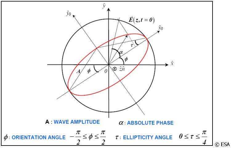
A particular graphical representation of the backscattering variation as a function of the polarization, known as polarization signature, is quite useful for describing the polarization properties of a target. The response consists of a plot of synthesized (and normalized) scattering cross sections as a function of the ellipticity (τ) and orientation (ϕ) angles of the received wave. Ellipticity (-45° to +45°) describes the flatness of the locus of the electric vector of a fully polarized wave, while orientation (-90° to +90°) is the angle between the major axis of the ellipse and a reference direction.
In addition to the estimation of the polarimetric signature of a point-target-like object, a search of the pixel location corresponding to the HH maximum intensity in a window surrounding the provided location of the point-target-like object is performed. In case the location of the point-target-like object is provided in cartographic co-ordinates, its expected initial location in slant range geometry is estimated through a backward-geocoding process using the nominal product header information. A refined target location is then obtained through a data interpolation process; the maximum backscatter value is identified over a window of about 15 pixels around the input target co-ordinates. An estimate of the residual polarimetric calibration errors, in terms of amplitude and phase imbalance, is provided assuming that the target is a corner reflector.
Input Files
Input HH File
Input file names of the scattering matrix (_slc). This file is mandatory.
Input HV File
Input file names of the scattering matrix (_slc). This file is mandatory.
Input VH File
Input file names of the scattering matrix (_slc). This file is mandatory.
Input VV File
Input file names of the scattering matrix (_slc). This file is mandatory.
DEM/Cartographic System
Output Projection
In case the Georeferenced Point flag is set, the following parameters are compulsory to define the Cartographic System:
State
Definition of the country or general projection systems.
Projection
Definition of the projection system of the selected State. In case that a general projection system is selected in State, the Projection is automatically set.
Ellipsoid
Definition of the ellipsoid. This is chosen according to the selected State and Projection.
Hemisphere
Definition of the hemisphere. This is chosen according to the selected State and Projection.
Zone
Definition of the zone. This is chosen according to the selected State and Projection.
Datum Shift Parameters
Definition of the datum shift parameters. These are chosen according to the selected State and Projection.
Reference Height
In case that the Digital Elevation Model is not used, a constant ellipsoidal height must be provided. Default Reference Height is 0.
Cartographic Parameters
The reference parameters for some projection systems (e.g. Stereographic, Polar Stereographic, Gnomonic, Mercator, Miller, Albers, etc.) can be set.
Parameters - Principal Parameters
Range (column) / X
Range or cartographic (X) co-ordinate of the pixel.
Azimuth (row) / Y
Azimuth or cartographic (Y) co-ordinate of the pixel.
Height / Z
Elevation of the pixel (only for georeferenced points).
Georeferenced Point
When setting this flag (i.e. target identification by cartographic co-ordinates), it is compulsory to set the appropriate Cartographic System.
Orientation Increment
Increment (in degrees) of the orientation angle.
Ellipticity Increment
Increment (in degrees) of the ellipticity angle.
Estimate Theoretical
By setting this flag, an estimate of the theoretical polarimetric signature is calculated.
Parameters - Global
It brings to the general section of the Preferences parameters. Any modified value will be used and stored for further processing sessions.
Parameters - Other Parameters
It brings to the general section of the Preferences parameters. Any modified value will be used and stored for further processing sessions.
Output Files
Output Root Name
Root file name. It is also needed if a previously generated signature has to be re-loaded. This file is mandatory.
_co_signature
Co-polar signature with the associated header files (.sml, .hdr).
_cross_signature
Cross-polar signature with the associated header files (.sml, .hdr).
_co_signature.jpg
View of the Co-polar signature graph (jpeg format).
_cross_signature.jpg
View of the Cross-polar signature graph (jpeg format).
_signature.txt
Estimate of the residual polarimetric calibration errors.
Details specific to the Units of Measure and Nomenclature of the output products can be found in the Data Format section.
General Functions
Exec
The processing step is executed.
Store Batch
The processing step is stored in the batch list. The Batch Browser button allows to load the batch processing list.
Close
The window will be closed.
Help
Specific help document section.
Specific Function(s)
None.
References
ESA, Polarimetric SAR Interferometry tutorial
Van Zyl, J.J., H. Zebker, and C. Elachi, 1987: "Imaging Radar Polarization Signatures: Theory and Application". Radio Science, vol. 22, no. 4, pp. 529-543.
W. Cameron, N. Youssef and L. Leung: "Simulated polarimetric signatures of primitive geometrical shapes". Geoscience and Remote Sensing, IEEE Transactions on, vol. 34, no. 3, May 1996, pp. 793 - 803.